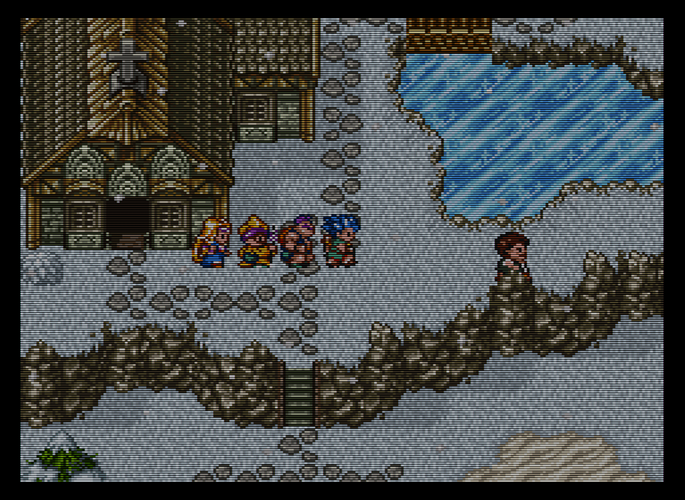
Shader logic- would this work?

Assume we are using the aperture grille RGB pattern, each phosphor is one pixel wide.

I’m trying to come up with something that will replicate phosphor behavior on a CRT by comparing the two closest same-color phosphors to a phosphor X and if one of them is brighter, change the luminosity value of X to the average of X and the value of the closest and brightest same-color phosphor. Basically, I’m trying to smooth out the transitions between bright phosphors and adjacent dark phosphors.

For every pixel:

(For pixel X located at x/y, find the luminance values for:

A: x+3,y+0

B: x-3,y+0.

Luminance value of X = p

(If luminance of A is greater than X and B, find the average of the luminance values of A and X to equal q. Change p to q.)

(If luminance of B is greater than X and A, find the average of the luminance values of B and X to equal q1. Change p to q1.))

Will this logic work?

Something like this probably already exists, right?

Also, I’m not totally sure if just changing the luminance values is what I want to do. Just toying with some ideas.

1 Like

logically, sure. Dunno how it would look, but it’s doable in a shader.

1 Like

A section of one line at 5x scale, with scanlines applied.

image_1

Here’s what happens if I apply the above logic.

image_2

It’s extremely subtle and I have no idea if this would even look good. Maybe I’ll give it a shot, though… Just trying to make those transitions a little less harsh/more natural looking.

1 Like

hmm, yeah, that didn’t really have the desired effect, even after correcting the chroma values.

I think the problem with doing that based on luma is that luma differences don’t capture differences between colors very well (which sounds more obvious as I’m typing it…). That is, the perceptual difference between bright green (vec3(0.,1.,0.) and bright red (vec3(1.,0.,0.) is huge, but their luma difference is not nearly so large.

I tried converting to luma, doing a 3px horizontal gaussian blur and then replacing the original image’s luma with the blurred luma and rather than smoothing any transitions, it just made a fairly convincing bloom, which was kinda cool but not really what I/you wanted.

However, you might be able to take this idea and switch to another colorspace that better approximates the relationship you’re wanting to soften (maybe use the saturation component from HSV…?).

1 Like

https://mega.nz/#!Rsc3VSgL!Sz2QEhK8YZqrsqjhfohCF9jnz93ZTmG9g1jxtB0tmcE

Made it as a Quark GLSL shader, calling it Smooth Dilation or rather DilationSmooth since it’s kind of like dilation but smoother. The offsets use the output image size rather than the source size and I capped it at 1.0 pixel because it makes duplicate images otherwise, but you can use fractional sizes in the slider.

I think it has some usefulness, absolutely.

1 Like

Here’s a slang version:

#version 450

layout(push_constant) uniform Push
{
	vec4 SourceSize;
	vec4 OriginalSize;
	vec4 OutputSize;
	uint FrameCount;
	float SamplingDistance;
} params;

#pragma parameter SamplingDistance "Sampling Distance" 1.0 0.0 1.0 0.1

layout(std140, set = 0, binding = 0) uniform UBO
{
	mat4 MVP;
} global;

#pragma stage vertex
layout(location = 0) in vec4 Position;
layout(location = 1) in vec2 TexCoord;
layout(location = 0) out vec2 vTexCoord;

void main()
{
   gl_Position = global.MVP * Position;
   vTexCoord = TexCoord;
}

#pragma stage fragment
layout(location = 0) in vec2 vTexCoord;
layout(location = 0) out vec4 FragColor;
layout(set = 0, binding = 2) uniform sampler2D Source;

void main()
{
    vec2  Offsets  = vec2(params.OutputSize.z * params.SamplingDistance,0.0);
    vec3  PictureX = texture(Source,vTexCoord).xyz;
    float LumX     = ((0.299*PictureX.x) + (0.587*PictureX.y) + (0.114*PictureX.z));
    vec3  PictureA = texture(Source,vTexCoord+Offsets).xyz;
    float LumA     = ((0.299*PictureA.x) + (0.587*PictureA.y) + (0.114*PictureA.z));
    vec3  PictureB = texture(Source,vTexCoord-Offsets).xyz;
    float LumB     = ((0.299*PictureB.x) + (0.587*PictureB.y) + (0.114*PictureB.z));

    vec3 MergeXAB  = mix(PictureX,mix(PictureA,PictureB,greaterThan(vec3(LumB),vec3(LumA))),float(max(LumB,LumA)>LumX)*0.5);
    FragColor = vec4(MergeXAB,1.0);
}
1 Like

Looking forward to checking these out when I get home!

Since it’s going to be a few days before I can actually get home and test anything out, just wanted to share something that occurred to me: altering the value dimension in HSV might result in something close to the desired effect, since it determines how much white/black is added.

Current scanline effects mimic beam width variation by adding a certain amount of white/black to the rows of pixels that make up a scanline. I think it should be possible to mimic some phosphor dynamics by doing something similar.

Got the test working fine, but how do I actually use the shader file? :sweat_smile:

A few questions/comments:

  1. Is there some bilinear filtering being applied to the test images before I add dilation smooth? It seems a little smooth even before applying dilation smooth.

  2. I’m trying to average the two closest same-color “phosphors” and if one is brighter, change the darker one to the average. If I have the aperture grille effect applied, set the integer scale to 6x5, and set sampling distance to 0.5, does this result in the desired effect? Just not 100% clear on what “sampling distance” is referring to.

  3. Will this effect stack with the aperture grille effect in the desired way? That is, will it compare and alter the values of the pixels after the RBG aperture grille effect is applied?

  4. When you get the time, it would be nice to see a shader that does the same thing as this, but which alters the value component from HSV (rather than luma).

Thanks for the contributions! Really like the work you’ve done.

Here’s an example using the above logic but substituting “value” from HSV for luma. This is a section of one scanline at 5x scale with scanlines applied. This should smooth out the transitions between bright and dark “phosphors” and brighten up the image some.

Original: image_1

With logic applied: img_2

If that’s the effect you want then you should make the pixels underneath the overlay brighter first. That’s the easiest fix.

Ah, yeah. It didn’t occur to me that this would be easier and have the same effect. :sweat_smile: If/when you get the time, it’d be nice to see a demo showing the results of changing “value” from the HSV colorspace instead of changing luma.

edit: eh, I played around in GIMP and changing “value” looks weird. Back to the drawing board. Maybe I need to change the brighter of the two pixels to the average…?

It’d look like this.

Hmm, that’s not really the intended effect, haha. :stuck_out_tongue: Just kinda gives everything a weird halo. Thanks for the demo!

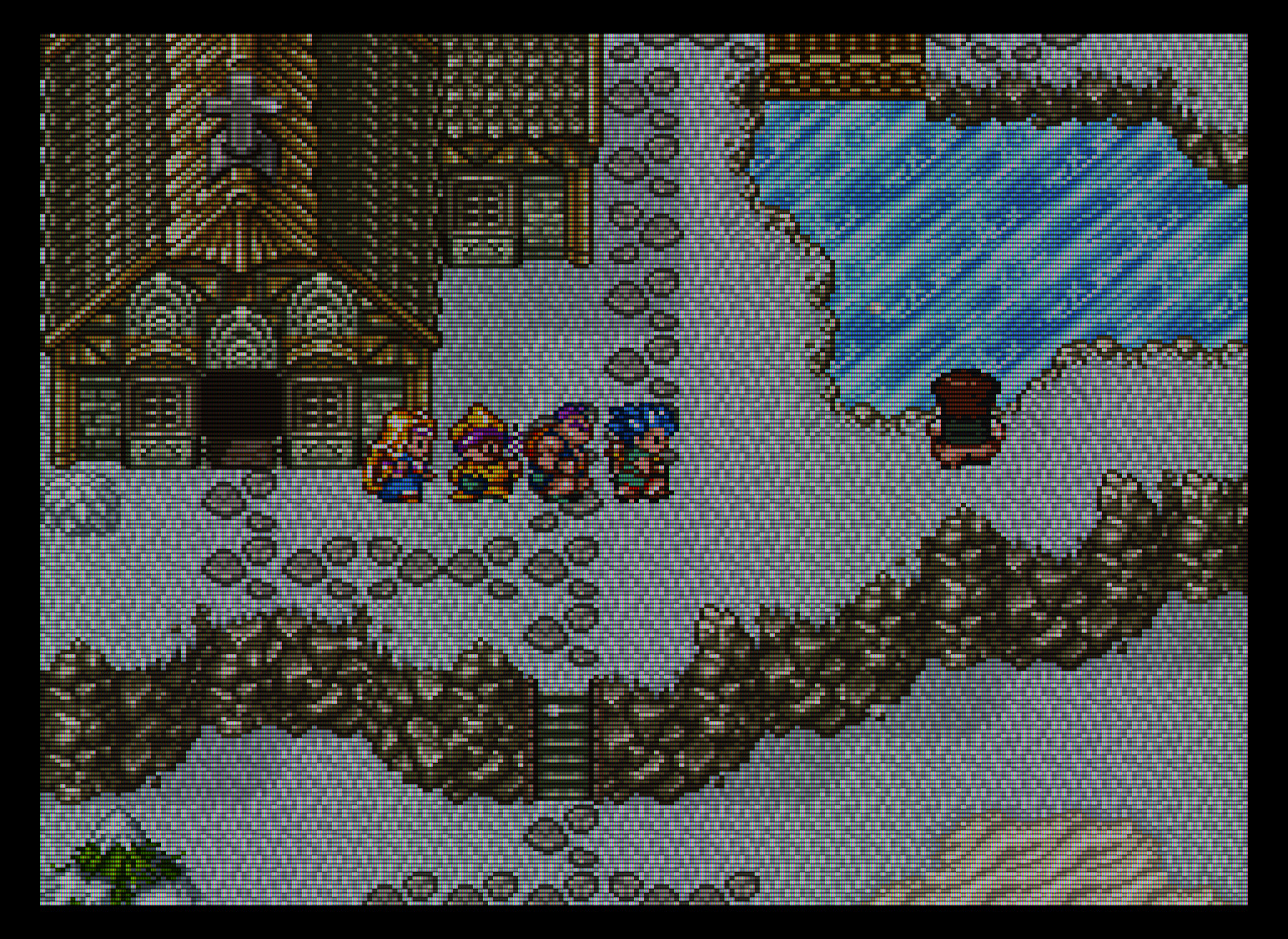
I think, instead, that the brighter of the two compared pixels should be changed to the average.

Also, it might not be possible to get the intended effect by just altering one value. It might make more sense to find the average color values of two adjacent different-color pixels, then change the brighter of the two pixels so that its color values match the averages.

Just to clarify, the intended effect can be seen in the shot below. When a bright color transitions to a darker color on the same scanline, such as white adjacent to black, the line shrinks in width where the brighter color meets the darker color. This gives the scanlines (visible lines) a “rounded” edge, which is especially noticeable wherever there is a black border, such as around Yoshi below.

It seems like it should be possible to recreate this effect via a scanline overlay and the right logic to brighten/darken adjacent different-color pixels. Maybe (probably) this is a lot more complicated than I’m assuming.

It occurs to me that maybe what I need is just a simple blur. :sweat_smile:

The first image below is with just the RGB and scanline overlay, shader filter set to nearest. The second image has added some very slight horizontal blur from modified Quilez scaling, with the x-axis blur parameter set to 0.00 and shader filter set to linear. This is from the zfast_crt shader.

Here’s a close up of Yoshi for the sake of comparison. Obviously, the phosphors are a lot chunkier in the below shot compared to the shot of Yoshi on a BVM in my previous post (pretty sure that’s a BVM). It’s close enough to the desired effect, and I’m not sure it’s possible to do much better without higher resolutions.

img_1

2 Likes