haha, I was thinking I would be able to just figure this out by looking at the code. How very wrong I was. 
I know you’re probably busy, and don’t expect you to get to it anytime soon, but any chance I could ask you for another favor…? 

haha, I was thinking I would be able to just figure this out by looking at the code. How very wrong I was.
I know you’re probably busy, and don’t expect you to get to it anytime soon, but any chance I could ask you for another favor…?
Here you go:
/*
    zfast_crt_standard - A simple, fast CRT shader.

    Copyright (C) 2017 Greg Hogan (SoltanGris42)

    This program is free software; you can redistribute it and/or modify it
    under the terms of the GNU General Public License as published by the Free
    Software Foundation; either version 2 of the License, or (at your option)
    any later version.


Notes:  This shader does scaling with a weighted linear filter for adjustable
	sharpness on the x and y axes based on the algorithm by Inigo Quilez here:
	http://http://www.iquilezles.org/www/articles/texture/texture.htm
	but modified to be somewhat sharper.  Then a scanline effect that varies
	based on pixel brighness is applied along with a monochrome aperture mask.
	This shader runs at 60fps on the Raspberry Pi 3 hardware at 2mpix/s
	resolutions (1920x1080 or 1600x1200).
*/

//For testing compilation
//#define FRAGMENT
//#define VERTEX

//This can't be an option without slowing the shader down
//Comment this out for a coarser 3 pixel mask...which is currently broken
//on SNES Classic Edition due to Mali 400 gpu precision
//#define FINEMASK
//Some drivers don't return black with texture coordinates out of bounds
//SNES Classic is too slow to black these areas out when using fullscreen
//overlays.  But you can uncomment the below to black them out if necessary
//#define BLACK_OUT_BORDER

// Parameter lines go here:
#pragma parameter BLURSCALEX "Blur Amount X-Axis" 0.30 0.0 1.0 0.05
#pragma parameter LOWLUMSCAN "Scanline Darkness - Low" 6.0 0.0 10.0 0.5
#pragma parameter HILUMSCAN "Scanline Darkness - High" 8.0 0.0 50.0 1.0
#pragma parameter BRIGHTBOOST "Dark Pixel Brightness Boost" 1.25 0.5 1.5 0.05
#pragma parameter MASK_DARK "Mask Effect Amount" 0.0 0.0 1.0 0.05
#pragma parameter MASK_FADE "Mask/Scanline Fade" 0.8 0.0 1.0 0.05

#pragma parameter shadowMask "Mask Style" 3.0 0.0 4.0 1.0
#pragma parameter DOTMASK_STRENGTH "CGWG Dot Mask Strength" 0.3 0.0 1.0 0.01
#pragma parameter maskDark "Lottes maskDark" 0.5 0.0 2.0 0.1
#pragma parameter maskLight "Lottes maskLight" 1.5 0.0 2.0 0.1

#if defined(VERTEX)

#if __VERSION__ >= 130
#define COMPAT_VARYING out
#define COMPAT_ATTRIBUTE in
#define COMPAT_TEXTURE texture
#else
#define COMPAT_VARYING varying
#define COMPAT_ATTRIBUTE attribute
#define COMPAT_TEXTURE texture2D
#endif

#ifdef GL_ES
#define COMPAT_PRECISION mediump
#else
#define COMPAT_PRECISION
#endif

COMPAT_ATTRIBUTE vec4 VertexCoord;
COMPAT_ATTRIBUTE vec4 COLOR;
COMPAT_ATTRIBUTE vec4 TexCoord;
COMPAT_VARYING vec4 COL0;
COMPAT_VARYING vec4 TEX0;
COMPAT_VARYING float maskFade;
COMPAT_VARYING vec2 invDims;

vec4 _oPosition1;
uniform mat4 MVPMatrix;
uniform COMPAT_PRECISION int FrameDirection;
uniform COMPAT_PRECISION int FrameCount;
uniform COMPAT_PRECISION vec2 OutputSize;
uniform COMPAT_PRECISION vec2 TextureSize;
uniform COMPAT_PRECISION vec2 InputSize;

// compatibility #defines
#define vTexCoord TEX0.xy
#define SourceSize vec4(TextureSize, 1.0 / TextureSize) //either TextureSize or InputSize
#define OutSize vec4(OutputSize, 1.0 / OutputSize)

#ifdef PARAMETER_UNIFORM
// All parameter floats need to have COMPAT_PRECISION in front of them
uniform COMPAT_PRECISION float BLURSCALEX;
//uniform COMPAT_PRECISION float BLURSCALEY;
uniform COMPAT_PRECISION float LOWLUMSCAN;
uniform COMPAT_PRECISION float HILUMSCAN;
uniform COMPAT_PRECISION float BRIGHTBOOST;
uniform COMPAT_PRECISION float MASK_DARK;
uniform COMPAT_PRECISION float MASK_FADE;
uniform COMPAT_PRECISION float shadowMask;
uniform COMPAT_PRECISION float DOTMASK_STRENGTH;
uniform COMPAT_PRECISION float maskDark;
uniform COMPAT_PRECISION float maskLight;
#else
#define BLURSCALEX 0.45
//#define BLURSCALEY 0.20
#define LOWLUMSCAN 5.0
#define HILUMSCAN 10.0
#define BRIGHTBOOST 1.25
#define MASK_DARK 0.0
#define MASK_FADE 0.8
#define shadowMask 3.0
#define DOTMASK_STRENGTH 0.3
#define maskDark 0.5
#define maskLight 1.5
#endif

void main()
{
    gl_Position = MVPMatrix * VertexCoord;

	TEX0.xy = (TexCoord.xy);
	maskFade = 0.3333*MASK_FADE;
	invDims = 1.0/TextureSize.xy;
}

#elif defined(FRAGMENT)

#ifdef GL_ES
#ifdef GL_FRAGMENT_PRECISION_HIGH
precision highp float;
#else
precision mediump float;
#endif
#define COMPAT_PRECISION mediump
#else
#define COMPAT_PRECISION
#endif

#if __VERSION__ >= 130
#define COMPAT_VARYING in
#define COMPAT_TEXTURE texture
out COMPAT_PRECISION vec4 FragColor;
#else
#define COMPAT_VARYING varying
#define FragColor gl_FragColor
#define COMPAT_TEXTURE texture2D
#endif

uniform COMPAT_PRECISION int FrameDirection;
uniform COMPAT_PRECISION int FrameCount;
uniform COMPAT_PRECISION vec2 OutputSize;
uniform COMPAT_PRECISION vec2 TextureSize;
uniform COMPAT_PRECISION vec2 InputSize;
uniform sampler2D Texture;
COMPAT_VARYING vec4 TEX0;
COMPAT_VARYING float maskFade;
COMPAT_VARYING vec2 invDims;

// compatibility #defines
#define Source Texture
#define vTexCoord TEX0.xy
#define texture(c, d) COMPAT_TEXTURE(c, d)
#define SourceSize vec4(TextureSize, 1.0 / TextureSize) //either TextureSize or InputSize
#define OutSize vec4(OutputSize, 1.0 / OutputSize)

#ifdef PARAMETER_UNIFORM
// All parameter floats need to have COMPAT_PRECISION in front of them
uniform COMPAT_PRECISION float BLURSCALEX;
//uniform COMPAT_PRECISION float BLURSCALEY;
uniform COMPAT_PRECISION float LOWLUMSCAN;
uniform COMPAT_PRECISION float HILUMSCAN;
uniform COMPAT_PRECISION float BRIGHTBOOST;
uniform COMPAT_PRECISION float MASK_DARK;
uniform COMPAT_PRECISION float MASK_FADE;
uniform COMPAT_PRECISION float shadowMask;
uniform COMPAT_PRECISION float DOTMASK_STRENGTH;
uniform COMPAT_PRECISION float maskDark;
uniform COMPAT_PRECISION float maskLight;
#else
#define BLURSCALEX 0.45
//#define BLURSCALEY 0.20
#define LOWLUMSCAN 5.0
#define HILUMSCAN 10.0
#define BRIGHTBOOST 1.25
#define MASK_DARK 0.25
#define MASK_FADE 0.8
#define shadowMask 3.0
#define DOTMASK_STRENGTH 0.3
#define maskDark 0.5
#define maskLight 1.5
#endif

#define mod_factor vTexCoord.x * SourceSize.x * OutSize.x / SourceSize.x

// Shadow mask.
vec3 Mask(vec2 pos)
{
   vec3 mask = vec3(maskDark, maskDark, maskDark);

   // Very compressed TV style shadow mask.
   if (shadowMask == 1.0)
   {
      float line = maskLight;
      float odd  = 0.0;

      if (fract(pos.x/6.0) < 0.5)
         odd = 1.0;
      if (fract((pos.y + odd)/2.0) < 0.5)
         line = maskDark;

      pos.x = fract(pos.x/3.0);

      if      (pos.x < 0.333) mask.r = maskLight;
      else if (pos.x < 0.666) mask.g = maskLight;
      else                    mask.b = maskLight;
      mask*=line;
   }

   // Aperture-grille.
   else if (shadowMask == 2.0)
   {
      pos.x = fract(pos.x/3.0);

      if      (pos.x < 0.333) mask.r = maskLight;
      else if (pos.x < 0.666) mask.g = maskLight;
      else                    mask.b = maskLight;
   }

   // Stretched VGA style shadow mask (same as prior shaders).
   else if (shadowMask == 3.0)
   {
      pos.x += pos.y*3.0;
      pos.x  = fract(pos.x/6.0);

      if      (pos.x < 0.333) mask.r = maskLight;
      else if (pos.x < 0.666) mask.g = maskLight;
      else                    mask.b = maskLight;
   }

   // VGA style shadow mask.
   else if (shadowMask == 4.0)
   {
      pos.xy = floor(pos.xy*vec2(1.0, 0.5));
      pos.x += pos.y*3.0;
      pos.x  = fract(pos.x/6.0);

      if      (pos.x < 0.333) mask.r = maskLight;
      else if (pos.x < 0.666) mask.g = maskLight;
      else                    mask.b = maskLight;
   }

   return mask;
}

void main()
{

	//This is just like "Quilez Scaling" but sharper
	COMPAT_PRECISION vec2 p = vTexCoord * TextureSize;
	COMPAT_PRECISION vec2 i = floor(p) + 0.50;
	COMPAT_PRECISION vec2 f = p - i;
	p = (i + 4.0*f*f*f)*invDims;
	p.x = mix( p.x , vTexCoord.x, BLURSCALEX);
	COMPAT_PRECISION float Y = f.y*f.y;
	COMPAT_PRECISION float YY = Y*Y;

#if defined(FINEMASK)
	COMPAT_PRECISION float whichmask = fract( gl_FragCoord.x*-0.4999);
	COMPAT_PRECISION float mask = 1.0 + float(whichmask < 0.5) * -MASK_DARK;
#else
	COMPAT_PRECISION float whichmask = fract(gl_FragCoord.x * -0.3333);
	COMPAT_PRECISION float mask = 1.0 + float(whichmask <= 0.33333) * -MASK_DARK;
#endif
	COMPAT_PRECISION vec3 colour = COMPAT_TEXTURE(Source, p).rgb;

	COMPAT_PRECISION float scanLineWeight = (BRIGHTBOOST - LOWLUMSCAN*(Y - 2.05*YY));
	COMPAT_PRECISION float scanLineWeightB = 1.0 - HILUMSCAN*(YY-2.8*YY*Y);

#if defined(BLACK_OUT_BORDER)
	colour.rgb*=float(tc.x > 0.0)*float(tc.y > 0.0); //why doesn't the driver do the right thing?
#endif

	FragColor.rgb = colour.rgb*mix(scanLineWeight*mask, scanLineWeightB, dot(colour.rgb,vec3(maskFade)));
	FragColor.rgb = pow(FragColor.rgb, vec3(2.2,2.2,2.2));
   float dotmask = 1.0 - DOTMASK_STRENGTH;

   //cgwg's dotmask emulation:
   //Output pixels are alternately tinted green and magenta
   vec3 dotMaskWeights = mix(vec3(1.0, dotmask, 1.0),
                             vec3(dotmask, 1.0, dotmask),
                             floor(mod(mod_factor, 2.0)));
   if (shadowMask == 0.)
   {
      FragColor.rgb *= dotMaskWeights;
   }
   else
   {
      FragColor.rgb *= Mask(floor(1.000001 * gl_FragCoord.xy + vec2(0.5,0.5)));
   }

	FragColor.rgb = pow(FragColor.rgb, vec3(1./2.2,1./2.2,1./2.2));

}
#endifHello and thankyou for the reply.
I understand now, what I did wrong was after adding the xbrz pass, I edited the shader 1 instead of adding another preset.
Thanks for the guide, it looks epic now.
Zfast+dotmask is probably the best shader I have tried to date in terms of picture quality and performance. It should definitely be added to the main shader repository! There were a couple things, though:
Is the mask effect from zfast redundant with the aperture grille effect from dotmask shader (mask effect 2.00)? They appear to be different, so it’s probably worth it to keep both. The one from dotmask shader looks better IMO, since it actually replicates the RGB phosphors. The one from zfast simply darkens every third vertical line, which looks more like an LCD grid to me.
I couldn’t get mask effect 4.00 to look right under any circumstances because the scanlines from zfast don’t line up with the phosphors, regardless of what scale I’m using. Even if you could get the scanlines to line up with the phosphors, this would look the same as aperture grille but with each phosphor two pixels wide instead of one, effectively turning the display into an aperture grille with less than 200 TVL  EDIT: I just realized this effect could be good for emulating old computer stuff that wasn’t 240p and didn’t have scanlines, so I suppose it’s best to leave it in there.
Here are my current shader settings, btw. Looks absolutely amazing with my LCD backlight at 100%.
X-axis blur: 0.00
scanline darkness low: 10.00
scanline darkness high: 50.00
mask effect: 0.00
mask/scanline fade: 1.00
dark pixel bright boost: 1.00
lottes mask effect: 3.00
lottes mask strength dark: 0.60
lottes mask strength light: 1.80
Hey! Do you mind posting some screenshots? Curious in your config outcome. 
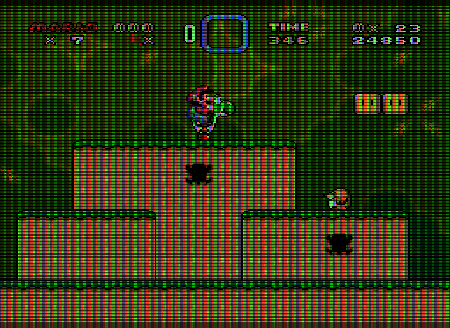
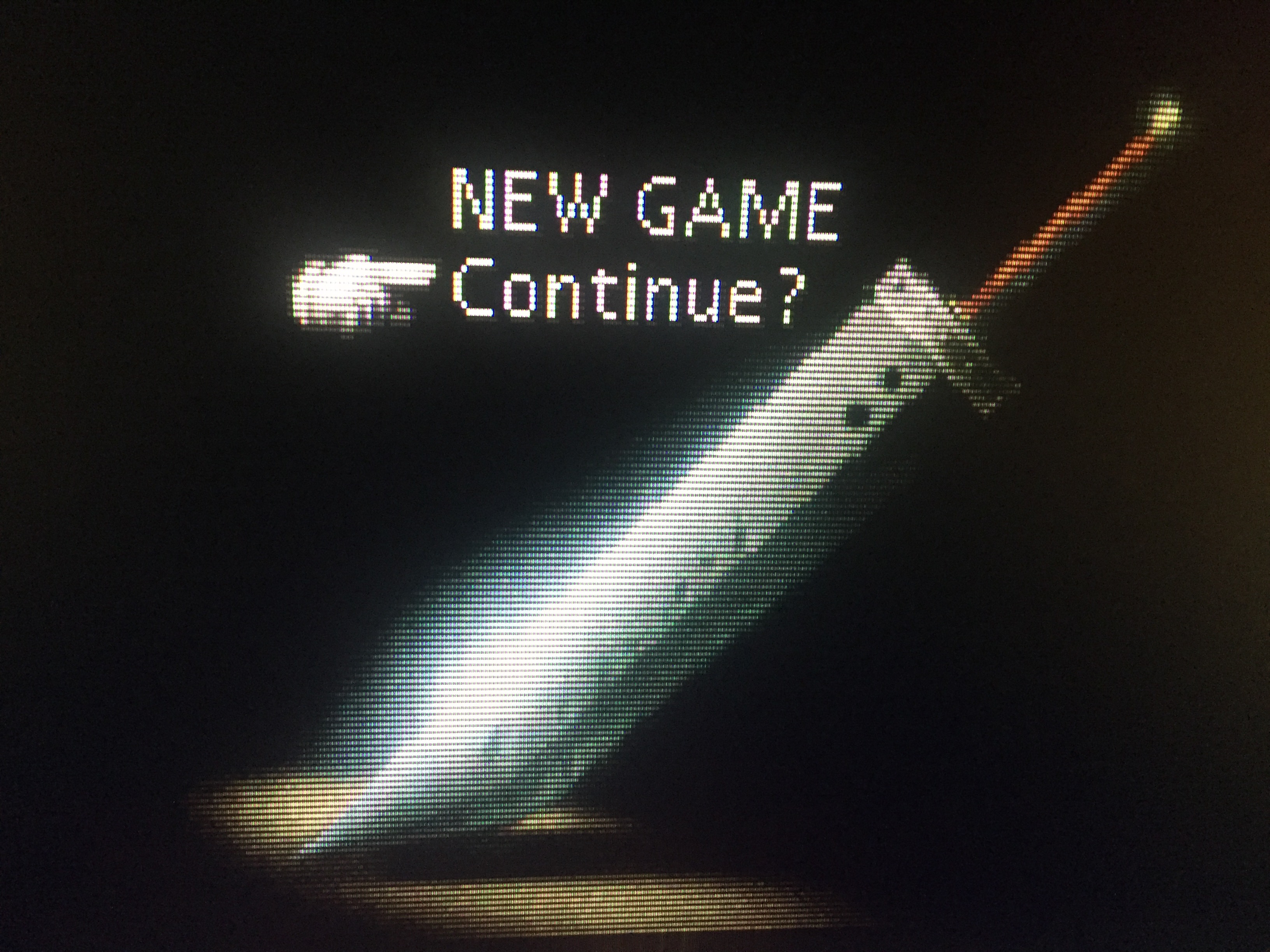
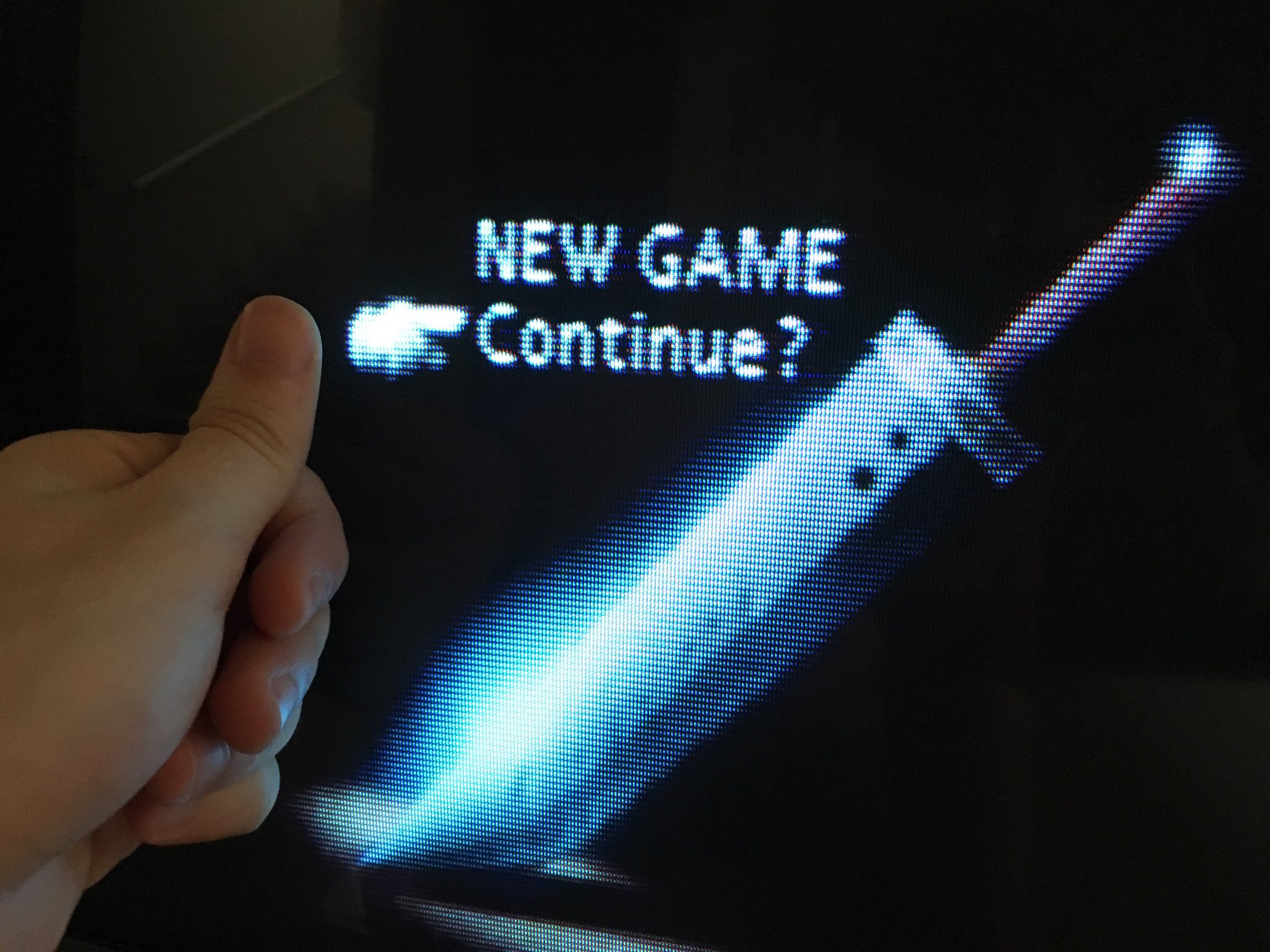
These were all taken at 5x vertical integer scale. You’ll have to click once to zoom, click “download image”, then open the image in an image editor and zoom to 100%. Or you can click once to zoom, then right click and select “view image,” then click once to zoom to 100%.  LCD backlight should be adjusted to 100% and all the room lights should be turned off
I think this does a pretty good job of approximating a very high TVL shadowmask CRT without any of the fake bloom, glow, or altered colors you see in many CRT shaders. IMO it looks very similar to a high resolution PC VGA CRT. Very sharp, but still nowhere near as sharp as a 1080p LCD.
These shots were taken with X-axis blur set to 40.00, but I’ve since adjusted this to 0.25, which I think looks better at normal viewing distances.
Looks great. Really nice work.
Thanks! I spend far too much time playing with shaders. You actually need to click once to zoom, then right click to view image and zoom to 100%, but I guess you figured that out
After playing with the Lottes shadowmask for a while, I eventually became annoyed by the presence of hard cut-offs right in the middle of a phosphor (ie, only half of a phosphor “lights up”). I’ve concluded that this effect requires accurate phosphor glow emulation in order to look right, making the shadowmask effect unsuitable for a lightweight approach.
However! Using the aperture grille RGB effect from the dotmask shader, in conjunction with zfast, produces some of the best results I’ve yet seen from a shader in my many years of playing with shaders/filters. This accurately recreates the scanlines and phosphors of a “perfect” 360 TVL aperture grille CRT without any additional blur or exaggerated effects (which I’m not a fan of). Here are the changes I’ve made to the shader and parameter settings:
Shader #0: image-adjustment
Shader #0 filter: don’t care
Shader #0 scale: don’t care
Shader #1: zfast_CRT+dotmask
Shader #1 filter: nearest
Shader #1 scale: don’t care
changes to parameter settings:
ia_monitor_gamma = “2.200000”
ia_target_gamma = “2.400003”
BLURSCALEX = “0.000000”
BRIGHTBOOST = “1.000000”
DOTMASK_STRENGTH = “0.300000”
HILUMSCAN = “8.000000”
LOWLUMSCAN = “9.000000”
MASK_DARK = “0.000000”
MASK_FADE = “0.000000”
maskDark = “0.500000”
maskLight = “2.000000”
under “video options” bilinear filter is OFF, and integer scale is ON. Aspect ratio set to CUSTOM.
LCD backlight should be adjusted to 100% when using these settings.
example:
That looks great. Would you mind uploading the combined shader file?
If you scroll up to the last post made by HunterK, he posted the full text of the combined shader. Just need to make a new txt file and copy and paste, then save as “whatever.glsl” in the appropriate directory.
I understand that Hunter released the code for zfast_crt+dotmask.glsl but could you release your settings, I created my own copy of the shader by copy and pasting what he posted but I can’t find all the settings you are describing, even when opening the shader in notepad++.
Update: Alright I was able to find everything with the exception of: feedback_pass= “0” float_framebuffer0= “0”
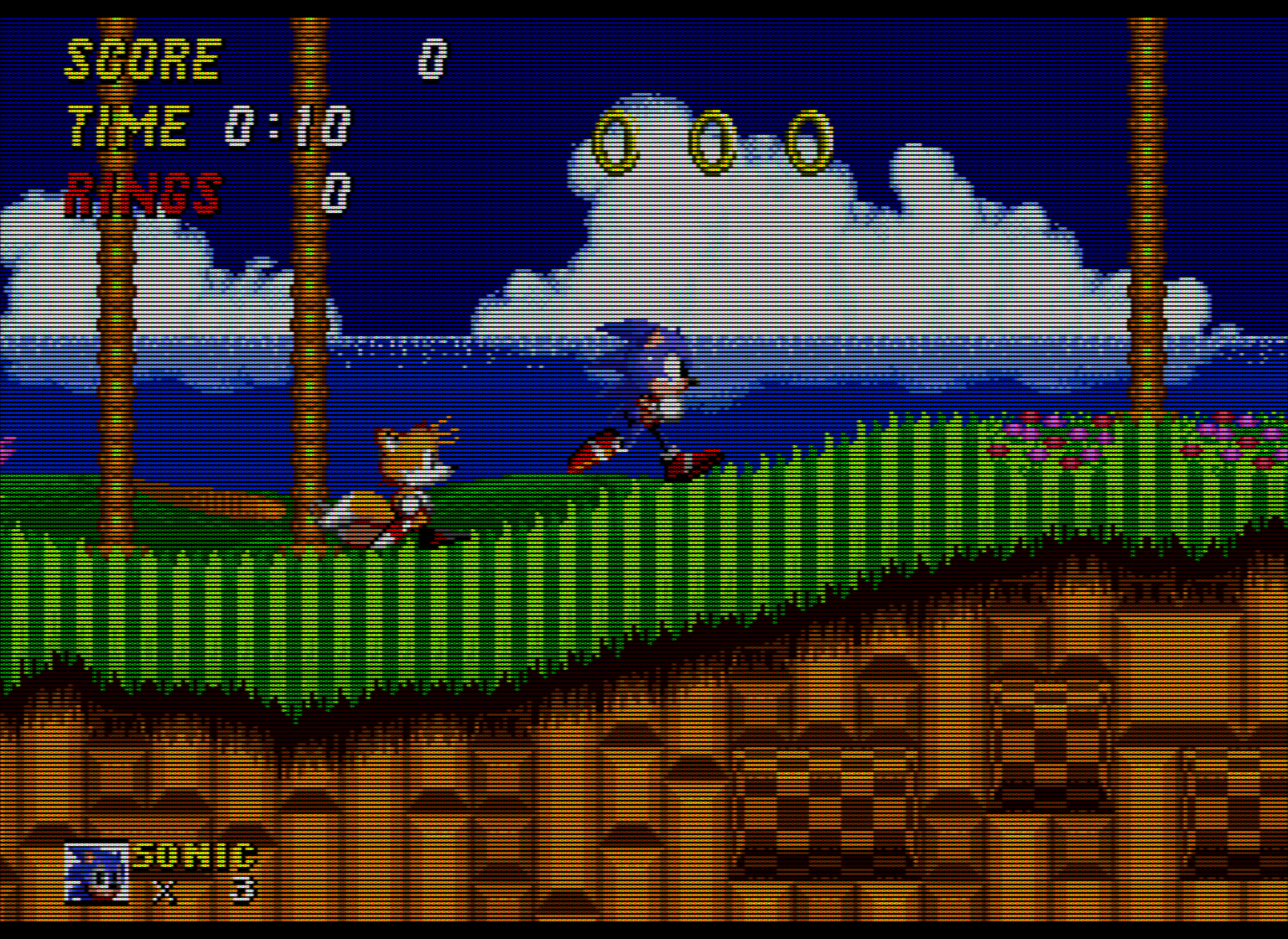
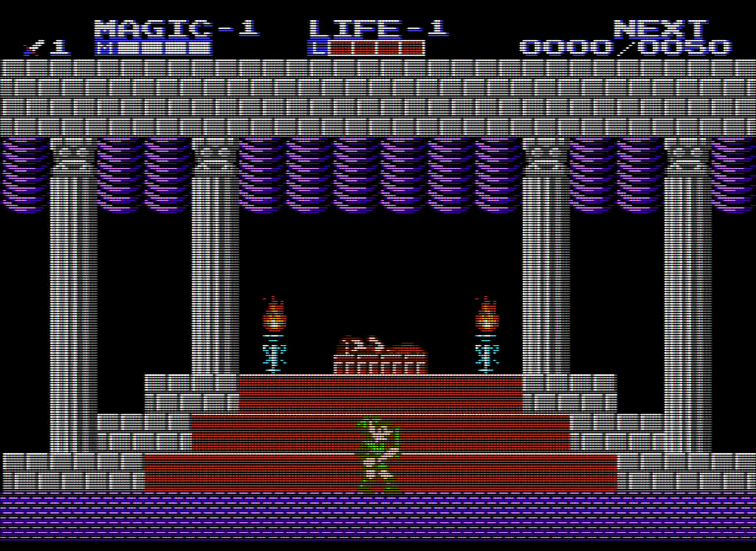
It does indeed, but… well who played the MegaDrive on hires computer monitors in 1991? More than half of the screen is pure black. If sharpness is the target well you said it yourself, a 1080p LCD will be sharper. Why then bother with black scanlines and shadowmasks?
I’m not interested in nostalgia or some dubious notion of “authenticity.” I’m interested in what actually improves the objective picture quality. If someone had offered me a high end RGB monitor in 1991, or if I was able to afford one, it would have been a no-brainer to go for the RGB CRT. It would have been slightly nuts to refuse the RGB CRT in 1991. Objective picture quality > nostalgia. As far as half of the screen being pure black… well, that’s what a CRT screen does. A CRT screen consists of mostly black space, with the image consisting of brightly colored dots.
Also, look at that RGB monitor used on the Toys R Us SNES display unit. Flat screen, check. RGB, check. Sharper than any consumer TV, check. This is in the early 90s.
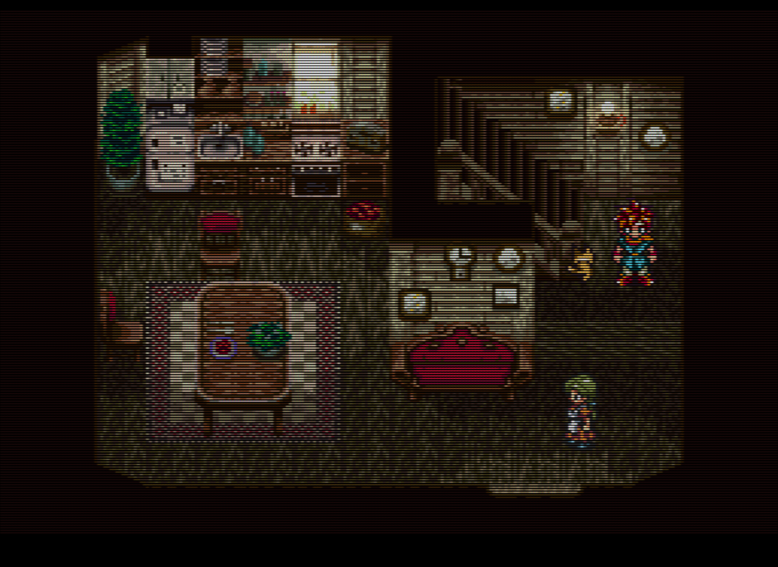
The scanlines and shadowmask are essential to recreating the native display environment for 240p content. Without scanlines, you’re looking at an image that is visually identical to a line-doubled image. Without the phosphor structure and lower TVL of the mask, the image is far too smooth (which may be counter-intuitive). The scanlines and mask are both essential for reducing the high-frequency content and makes the image much easier on the eyes, objectively. This relies on a well-known feature of the human visual system which is also seen in pointilist painting. 240p content was never meant to be displayed as raw pixels; it’s like nails on chalkboard for your eyes.
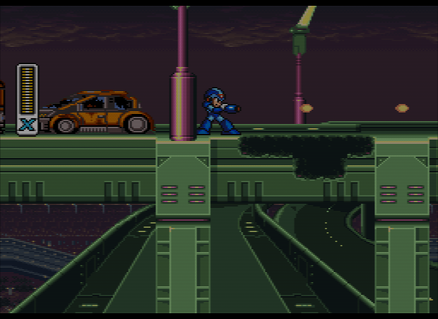
The image I posted immediately above is actually a nearly perfect recreation of a 360 TVL aperture grille CRT without any of the artifacts that people sought to eliminate on their CRTs. For reference, a 20" TV from the 80s or 90s was around 300 TVL. The only thing lacking is the mask strength, which can’t be increased any further without compromising too much on brightness. This actually looks more like a 20" Trinitron than any shader I’ve seen at 1080p.
At 1080p, you can’t add too much glow/bleed/blending without significantly reducing the emulated TVL, which winds up making the image look blurrier than any well-functioning consumer CRT ever was. At 720p you can just forget about mask emulation.
I think a lot of people are misidentifying what it is about a CRT screen that makes the image look better. CRTs weren’t blurry; they were lower resolution. A lower resolution image is not the same thing as a blurred image. People are mistakenly conflating blur with smooth appearance. A smooth-looking image is not the same thing as a blurry image, and an image on a CRT appeared smooth for reasons that have almost nothing to do with blur.
At 4k and higher resolutions we can have more accurate blending (really, 8k is needed to be truly accurate), but it becomes moot with HDR capable displays. With HDR you can create actual glow and blending by cranking up the brightness and getting the individual emulated phosphors in the RGB mask to glow as brightly as the real thing on a CRT.
Those two shouldn’t matter; you can just ignore those. 
Of course the scanlines and mask are essential, I never said or even implied that 240p content should be displayed raw (nails on chalkboard indeed!) but picture quality is both objective and subjective. And I think that the screen you posted, as accurate as it might be in let’s say scientific terms, is too sharp and dark. I wouldn’t want to play games that way. I’m also a huge fan of crt shaders, and to me something like this looks much nicer. But to each their own I suppose : )
Objectively, that shot you posted is actually far blurrier than any consumer CRT using a decent video signal. Subjectively, it looks nothing like any CRT I’ve seen in person. That much blur causes the eye to constantly strain to find the edges of objects, and would give me a headache after just a few minutes. I can’t stand bilinear filter or artificial blur. CRTs weren’t blurry like that; I’ve owned several over the years. I also have 20/20 vision, for reference. Also, the pincushion distortion stuff is really weird, that’s the kind of thing that you would typically try to eliminate via the service menu. Again, though, I’m not really motivated by nostalgia.
You suggest that the shot I posted is too dark - did you try adjusting your backlight to 100%, as I suggested? On my display (an ASUS VG248QE, for reference), doing so results in a peak brightness of around 200 cd/m2, which should provide plenty of “punch” in a room with a few lights turned on. Most CRTs had a maximum brightness that is slightly lower than this. This should also mitigate the sharpness when viewed at a normal viewing distance, since the human eye will blend things together when the emulated phosphors are objectively bright enough. Any LED-lit display should be capable of attaining adequate brightness with these settings.
Regarding sharpness, here’s the problem: at 1080p, you can only go up to 360 TVL, with each “phosphor” being one pixel wide on the LCD. The “glow” of a phosphor on a CRT is less wide than the width of an individual phosphor when viewed in extreme close-up. So we can’t actually add much (if any) glow at 1080p without either overly blurring the image or reducing the TVL. However, the next lowest TVL we can emulate at 1080p is 180 TVL, which is far lower than even the cheapest consumer CRTs. The solution is to create actual glow by cranking up the display backlight to 100% in order to get the emulated “phosphors” to output as much light power as the real thing on an actual CRT.
Furthermore, “glow” isn’t something that (just) happens directly on a CRT screen. It’s something that occurs somewhere between the surface of the screen and the eye of the observer. To have “accurate” glow, we need to replicate what a CRT screen is actually doing. A CRT is basically a very large amount of black space (more than half of the screen), with a bunch of very brightly colored tiny dots making up the image (or tiny slivers on an aperture grille). In terms of how a CRT screen actually works, I don’t see much room for improvement in the settings I posted. The mask strength could be improved, but only with a brighter display than the one I currently have.
I calibrate TVs as a hobby and occasionally as a side job. Very often, a calibrated image appears too dark to someone who is used to viewing their TV on “torch mode,” with the contrast and brightness set too high. The calibrated image shows more detail and is easier on the eyes. Sometimes it takes a few days before someone adjusts to the calibrated settings. Sometimes they just never see the benefit. A person might subjectively prefer an image that is objectively worse in terms of visible detail and eye strain. Even after being shown test patterns which prove the objective picture quality of the calibrated image is superior, they still don’t think it looks good for some subjective, non-scientific reason. In such a case, the problem doesn’t lie with the image, but with the visual-cognitive system of the observer.
I read the whole thing, I really appreciate your technical insight and I wish I could see your screen in person. No need to get defensive.
I’m not a screen calibrator, but I always work, play and see films on Spyder-calibrated screens, because what I am is a photographer and a videographer. So no, I’m not half blind as you seem to suggest. Again, videogaming is about as scientific as it is artistic. I admire your scientific approach (I really do), and I think there’s a lot of interesting stuff to learn from people like you. It’s just that from an artistic point of view, those ‘superior’ settings get in the way.
Do you play modern games like that? Do you watch films like that? Good for you if that’s the case, but I wouldn’t, for obvious reasons that can also be applied to retro gaming.
I didn’t mean to come off as defensive and I apologize if that’s the case.
It’s just that I’m not sure what you’re objecting to in the image I provided, unless you don’t like it for some mysterious subjective reason which is inherently difficult to articulate. Not much to talk about if that’s the case. You mentioned brightness earlier but unless you’re used to blasting your eyes with too much brightness and contrast, a peak brightness of 200 cd/m2 should be plenty bright in a room with average lighting conditions.
I’m not sure what you’re asking - I always watch films and play modern games on screens calibrated to the sRGB standard because it’s easier on the eyes and provides more accurate color and more detail, and is closest to what the creators intended you to see. Are you saying that you don’t watch movies or play games on a calibrated screen? Of course, I wouldn’t use the posted settings for modern games, if that’s what you mean. If you’ve found something you’re satisfied with, good for you, but I personally can’t understand why people would want to add so much artificial blur to their games. Blur isn’t why 240p content looks good on a CRT, IMO.
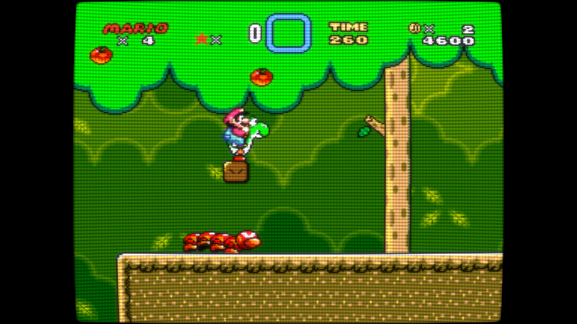
Here’s an image with a bit more blending/bloom between the scanlines, which may be more to your liking. Again, this will most likely require you to max out your display backlight to get an adequately bright image. There’s no alteration of the colors and no added blur or other artifacts added to “enhance” the picture. The scanlines here are a bit less than 1:1, which is probably closer to what you prefer, and the RGB mask strength has been increased somewhat. Actually, I think I might prefer this to my original shot.
I adjusted “maskDark” to 0.20 and “maskLight” to 2.00; this leads to a bit of clipping but it’s not too terrible and shouldn’t be noticeable when playing a game. I then changed “mask/scanline fade” to 0.60.
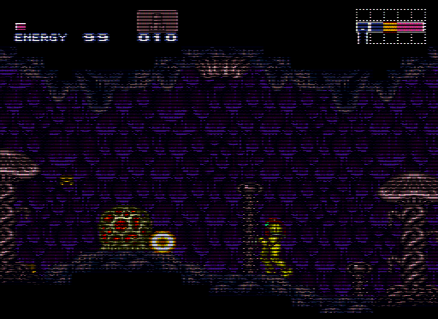
Here’s a comparison shot. Which one is the CRT and which one is the shader? Well, it’s pretty obvious due to the scaling artifacts that are currently unavoidable with PSX emulators, but if you ignore those, the two images are very close. Also bear in mind that the image of the CRT is overbloomed and the CRT would exhibit less bloom/glow when seen in person; a lot of that is added by the camera (scanlines should still be clearly visible over white on a properly calibrated screen), and I’m not confident that the CRT has been calibrated to the right colorspace. It’s also worth remembering that things look different in person than they do in photos. It’s really kind of amazing how cranking up the backlight on an LCD using these settings can approximate the glow and halation seen on a CRT, but that’s almost completely lost in the photo.
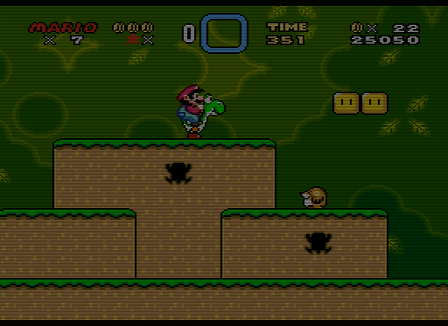
Here’s a gpu screenshot of the first image that does a better job of showing the mask and scanlines:
Does Retroarch support HDR? I would have imagined that Retroarch runs as SDR content, and therefore even on an HDR-capable display it would not take advantage of HDR peak brightness levels.
When this does become possible I agree that phosphor emulation will be very close to real phosphors.