I just realized that the magenta/green masks will NOT work properly with the mask_size parameter. If you increase the mask size with these masks then they will no longer map to the LCD subpixels correctly.
So, how do we bring down the TVL on a 4K display? If you use the magenta/green masks you get 1080 TVL- fine if you’re trying to emulate a BVM or a FW900, but not so great if going for a regular arcade monitor or a PVM.
The solution is to use one of these two masks cgwg described in the initial post:
Red, Green, Blue, Black
OR
Red, Yellow, Cyan, Blue
Both of these will lower the TVL to 540 on a 4K display, right around where you want it to be if trying to emulate a PVM.
For an 8K display… the TVL is 1080 with these two masks, which is fine if you’re trying to emulate a BVM or FW900; not so great if going for a PVM or arcade monitor. For 8K, we can use:
Red, Black, Green, Black, Blue, Black, Black
which lowers TVL to around 617.
However, the amount of lost brightness with this mask is insane at 8K - you have 3 active subpixels out of 21!
Even at 4K, the first mask above would result in a 75% reduction in brightness, too much to compensate for even with HDR.
The second mask, however, is only a 50% reduction in brightness (6 active subpixels out of 12); this is the one you want to use at 4K! (Red, Yellow, Cyan, Blue).
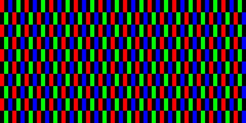
For a shadow mask, a simple magenta/green checkerboard pattern works well (although you get RBG instead of RGB). The LCD sub pixels used have a nice even spacing:
Probably only really useful on low resolution displays as the LCD subpixels will be too small to be visible at higher resolutions.
Thanks! This was actually covered in an earlier post. Kinda got buried, though
Depends on what TVL / dot pitch you’re trying to emulate and the resolution of the display being used. Masks were typically only visible on low TVL CRTs (televisions), and typically you had to get pretty close to the screen to notice. The mask still has an effect on the image even if it isn’t immediately visible at normal distances, though.
At 1080p this mask will result in 540 TVL which is right where you want it to be if you’re trying to emulate a PVM. At 4K it will result in 1080 TVL which is similar to a BVM or FW900.
A lower TVL is difficult to emulate accurately (with even spacing of the lcd subpixels). On a 720p display you get 360 TVL which is perfect if you’re trying to emulate a standard CRT TV. At 720p, however, you only have 3 pixels per scanline, which really limits what you can do with the scanline beam dynamics.
Also worth noting is that the display being used has to be displaying its native resolution for the mask to map to the subpixels correctly.
I was thinking 14" portable TV in a bedroom - although mainly from a 8-bit home computer perspective.
Those screens are Trinitrons so this mask isn’t applicable to them. However, it would be of use for those wanting to emulate old PC CRT displays.
I think it’s more in the ‘things to try’ category rather than something that will produce perfect results. If people are happy with the compromises involved with trying to do scanlines in 3 pixels it gives them another option.
I’ve been talking about aperture grille masks so much lately that I forgot what we were talking about
There are plenty of professional grade (500+ TVL) monitors that aren’t Trinitron/Aperture Grille, though, and plenty of 1000+ TVL dotmask monitors. I’m just not familiar with model numbers/names when it comes to those. At 1080p this pattern does a pretty god job of emulating an old PC CRT, and at 4K and higher would do a good job of emulating a higher resolution PC CRT. Like the aperture grille pattern, it would be 540 TVL @ 1080p and 1080 TVL @ 4K based on the number of “phosphor triads”.
Personally, I’m happy with the restrictions that come with trying to do even subpixel spacing with CRT masks, because I like the way that PVM and higher TVL CRTs look. Based on the number of “phosphors,” @1080p you can do 540 TVL; @4K you can do either 1080 TVL or 540 TVL
It’s kind of ironic, but to do a realistic emulation of a low TVL / pitch CRT with even spacing of the LCD subpixels actually requires at least 8K resolution, and you have to use the slotmask pattern.
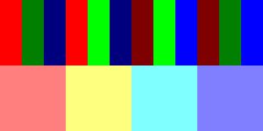
Don’t forget you can use the technique that some shaders currently use to increase the brightness - setting the subpixels that would be black to part of their full value.
e.g. The image below shows the red, yellow, cyan and blue mask with the value of the black subpixels increased to 50% of their full value - which would result in only a 25% overall reduction in brightness. The top half shows the subpixels, the bottom half the modified mask colours.
There’s a trade off between how bright the image is and how distinct the ‘phosphors’ appear, but it gives an option if the image is too dark to compensate for in other ways.
I was at CES 2020 and CES 2019 before the coronavirus pandemic.
One thing I noticed is that HDR is making screens brighter. If you’ve never seen HDR, you should watch “Coco” on a HDR screen to truly understand why 2,000, 5,000 nits and 10,000nit HDR screens actually make sense.
>1000-nit HDR is a savior of CRT emulation brightness
I saw a 10,000 nit Sony prototype screen at CES…and…WOW. It wasn’t too bright. Scenes looked normal, except things like streetlamps, sun glints, indicator lights, neon (<1% of pixels) with bright-as-reallife behavior. Holy hellish whiter-than-white highlights, absolutely beautiful.
They don’t hurt eyes – HDR nitroom is strategically milked for the “brightest 1%”, like brighter-than-white sun reflections off a chromed car, as well as neons at night, etc. It’s so jawdropping.
This becomes a massive silver lining for CRT emulation:
What this magically means, is that ultrabright screens means lots of HDR nitroom for emulation of CRTs both spatially and temporally. The use of 2,000 nit screens theoretically still allow 200 nits with temporally 80%-dark rolling-scan BFI (2,000nit->400 nit), combined with spatially 50%-black phosphor dot spacing. (400nit->200nit).
Delicious nitroom, to the rescue! Unfortunately these ultra-HDR screens are fiendishly expensive right now, but as manufacturing improves, these $10,000 4K IBM T-221’s of 2001 become those $299 Walmart 4K HDTV specials – the same is coming to Hz and HDR.
While a single HDR image may be brightness-clamped if there are too many ultrabright pixels in the same refresh cycle, the great news is that temporal emulation of a CRT solves this in a larger part – because only some pixels need to be shone extremely brightly, in a “rolling scan”. So those pixels stay bright, keeping APL constant per frame. The more refresh cycles available (240Hz+), the fewer HDR pixels need to be illuminated at a time, and the problem automagically solves itself as humankind approaches retina refresh rates.
Slow comodification of 120Hz already started (look at the new iPhone and Galaxy coming out), and commodification of 240Hz for non-gaming contexts will happen ~2025+, in the refresh rate race.
Temporal emulation of a CRT tube
I may also have a 240Hz monitor available for loan/gifting to any experienced developer willing to seriously take upon any of these projects:
Also, in addition to a free 240Hz loaner, an existing BountySource of approximately $500 may be applicable, see within those posts
Although spatial CRT emulation is part of this, this adds a temporal aspect (sub-refresh emulation of a CRT).
Although this is a long-term incubation, my vision is that the convergence of HDR (>1000nit) and ultra-Hz, will eventually happen as soon as CRTs become even more impossible to find in the 2030s+
Also, don’t count out LCD. I’ve seen kickass LCDs with less local-dim bloom than CRT phosphordot bloom from multithousand-LED count FALD mciroLED backlight sheets! Those are capable of >1000nit too, and likely will be only a $500 cost-add to a desktop monitor by roughly ~2025.
I believe that a future HDR’d 8K OLED/FALD/MicroLED at ultra-high true Hz (>240Hz, >2000nit, with a fake bezel and thick simulated lead glass in front), could pass the CRT Turing test (A/B test with a flat CRT tube) once both fully spatially emulated and temporally emulated.
Such a screen technology may not exist until 2030s… but the arrival or 360 Hz IPS monitors for Christmas 2021 means we now can do 6 refresh cycles per emulated 60Hz refresh cycle. And ASUS now has roadmapped a 1000Hz display this decade!
I’m Blur Busters – I see hundreds of displays, including displays of the future.
Since Blur Busters / TestUFO accumulates so many monitor samples over the years, this allows me to offer a single 240Hz monitor available at no additional cost – to a highly experienced emulator developer who’s willing to take upon a “Temporal HLSL” type project (I am located in Canada, so I’ll cover North America shipping; alas overseas shipping cost more than the price of the monitor).
Appealing to my hobbyist side, this is just a side project, a sort of X-Prize of emulation, with no deadline. Rising Hz lifts all boats, and I am extremely interested to see CRTs begun to be emulated temporally.
Very exciting stuff on the horizon, thanks for keeping us updated on these developments! Subpixel layout is a potential problem for CRT mask emulation as display technology advances, but it ceases to be an issue with very high DPI / retina resolution displays. I imagine that developer interest in implementing rolling scan will pick up as the technology to make it work becomes more widely available; right now it would be an extremely niche thing.
It certainly might be niche for now, so my posts is also aimed to get people at least thinking about it conceptually. This decade is the correct time to begin thinking about it, to an implementation arriving by 2025 (give or take a few years).
My aim is to create a basic TestUFO rolling-scan emulator (for 240Hz+ monitor demos) sometime during the course of this year – with a slow motion mode (single frame stepping operation) that can be viewed on any monitor. Essentially a scrolling horizontal bar on black background, with gamma-corrected alphablended overlaps (fuzzy-border) between adjacent frames to keep average pixel brightness consistent, without the tearing artifacts that occurs with sharp boundaries (non-fuzzed boundary), probably a CRT emulator version of moving photo ( www.testufo.com/photo )
This TestUFO rolling-scan CRT emulator would be very approximately akin to a software emulation of a high speed video of a CRT tube, and then when played in real time, looks just like a CRT ideally (within limitations of the refresh rate granularity, more Hz the merrier).
I understand how things work temporally very well (refresh rates, frame rates, GtG, MPRT, rasters, scanout, latency, etc), yet few people think temporals in addition to spatials.
1000-nit HDR is not scanline accurate. So it probably won’t give good results for CRT emulation shaders. Unless you have a per-pixel capable HDR display (would require an emissive display, like OLED o rMicro LED.)
Slotmask is 50% black space if you want an accurate slotmask emulation. Scanlines can reduce brightness by more than 50% depending on pixel color, but we’ll just call it 50%. Black frame insertion is another 50%.
So if we want our resulting image to be 100 nits, we need 100*2*2*2 = 800 nits.
However, contrast ratio is probably more important. There are home theater setups with like 50 nits and it’s fine in a totally dark room.
Cranking up the backlight on an LCD display will increase contrast but usually raises the black level at the same time. Emissive displays don’t have this problem, but they can suffer from burn-in and scanline patterns will cause uneven wear on the pixels. 500 nits with an emissive display is probably sufficient, but you have the problem of automatic brightness limiting on most of these displays.
It’s amazing and strangely nostalgic to see people developing this stuff. I remember daydreaming about all of this in the early-mid 90s after geeking out on tech specs of genesis vs snes and early lcd display tech and wondering where we would be in 25+ years
1000 nits is not enough but around 5000 to 10000 nits should be plenty for proper mask emulation + bfi/strobing/rolling scan + scanlines
You need a little bit more than 8k though. You need around 7416x5405 which is closer to ~9k or 10k really
Some Japanese dude on twitter who posts photos of his trinitron(Sony KV-14AF1) found this out
How is BFI a 95% reduction in brightness? 50% isn’t a random ballpark figure. If every other frame is black, doesn’t that result in a 50% reduction in brightness? This would seem like common sense, which of course is frequently wrong, but it would be nice to see some actual evidence supporting your claim.
Maybe it’s how their implementation works but from my experience with the LG C9, 30 OLED Light is 100 nits. With BFI, I had it at ~65 OLED Light. So yes, probably about 50% without knowing whether the setting is linear.