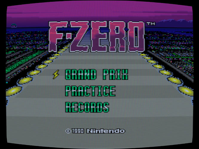
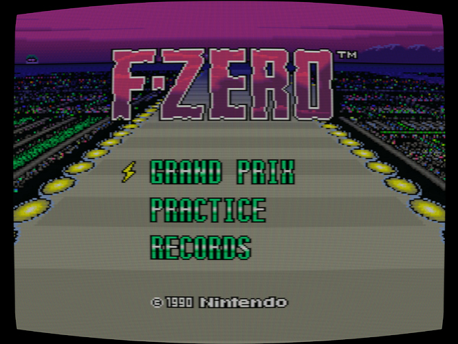
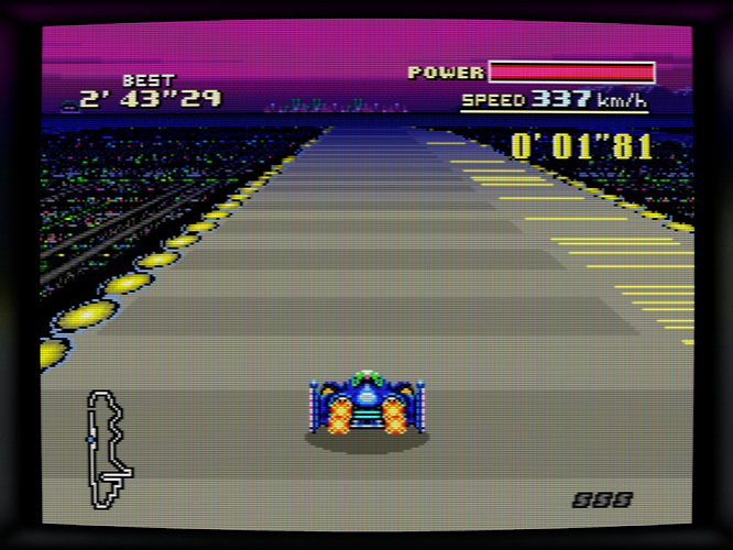
The Scanline Classic Shader

I’ve been playing around with masking methods. In order to avoid the pixel grid look, we have to do this:

  1. Filter the sampled input before applying the mask
  2. Apply the mask
  3. Filter again on upscale (or downscale)

This essentially creates two separate upscaling stages which makes the overall picture blurrier. However, we can at least control what filters we use at each stage. For now I am using bicubic filtering for both. However, it may be better to switch the second upscaler to Lanczos3 for more sharpness. The bicubic filter has been well-received as mimicking the beam spot.

The design parameter of the mask is TVL, but TVL is not well-defined in relation to a shadow mask, so I tried to keep it simple: 1 TVL is equal to one RGB cluster horizontally. I think this is the most intuitive definition because the patterns for the three shadow mask types (shadowmask, slot mask, aperture grille) are the same horizontally.

To get a better mask, black space is inserted around each dot in a pattern according to the mask. This is the spatial equivalent of ‘black frame insertion’ and does something to our perception to increase definition and clarity. The ‘black’ does not need to be the same as black level, simply being dark enough in relation to the bright dots is good enough. A feathering technique is used to reduce the black a bit and blend the dots a bit. This essentially acts as an anti-aliasing filter.

Aperture and shadow mask look okay, but slot mask has some issues I need to work out. Scanlines are present here but reduced to a 50% weight to provide more clarity to the mask. The TVL was set to 325 to represent a low-TVL screen, doable at 4K. A high TVL screen would need more resolution, but I am working on a grayscale mask that can support high TVL at a lower resolution (even if I had an 8K screen, I don’t think my video card would be able to support development of Scanline Classic on it). The shadow mask being darker is the correct behavior, but the slot mask is a little too light. The horizontal lines are too thin.

Shadow Mask

Slot Mask

Aperture Grille

5 Likes

Interesting shadow mask- normally each dot in the mesh is a single color (R, G or B) but here each dot contains a whole RGB triad. Is this intentional?

Also, have you considered how the subpixels will interact with the mask?

2 Likes

Each dot is a single color. The black space between dots creates a honeycomb effect because RGB dots aligned blend more as light than R blends with B. If the feathering is reduced, the dots become more distinct but at the cost of more moire.

Subpixel alignment requires assumptions about the colorspace and gamma of the output display. The use of dark regions is intended to reduce the effect the subpixel alignment would have as much as possible.

1 Like

I don’t think you need a higher resolution screen to simulate a high TVL.

I find the dots to be too tall and large in this mask. There’s no need to reinvent the wheel when it comes to mask implementation. There has been a lot of science, research, discussion and development on that front and different approaches have been successfully taken by CRT-Geom, CRT-Guest-Advanced, Koko-AIO, Sony Megatron Colour Video Monitor, CRT-Royale and more.

Please zoom in and take a look at the masks in these screenshots:

1 Like

This is just a WIP. The exact number of dots and the shape of the dots needed to be adjusted for aspect ratio. When I post some more screenshots tomorrow you’ll see the shadow mask dots come out circular.

The goal for this mask technique is to be input and output resolution independent. The only true-to-life parameters aside from the mask type are the TVL and the dot order (RGB, BGR, etc.). I could have used dot pitch, but that’s messy because it scales to the size of the actual screen and it’s fiddly to have to put in sizes. So I chose to make TVL correspond to number of dots horizontally. This is arbitrary; different manufacturers have different definitions of TVL, so I went with Sony’s definition where TVL is simply the number of horizontal phosphor triads on the screen.

Each triad requires six samples to resolve purely because there are black samples in between each dot, so for 4K screen at 4:3, 2880 / 6 = 480 TVL, medium TVL. However we can use a higher TVL if we allow for blending the dots, so I implemented that. And with the dot blending I can get up to a higher TVL. The dot blending also reduces brightness loss and I think that is very good for people still on SDR. Scanline Classic will still be an SDR shader and even if I get to implementing HDR down the road I still want to make this accessible in SDR and 1080p use cases.

There is also the marriage with the geometry technique. Geometry has to be applied both before and after the mask, so the mask has to be able to cope with that without breaking down (this is another reason why subpixel rendering will have to be ignored; with screen curvature means the subpixel antialiasing has to be calculated for each individual pixel).

3 Likes

Here is the almost complete pipeline rendering for RGB, just missing color correction and bezel. The geometry needs some tuning. Phosphor tails are maybe too strong…

2 Likes

Interesting. Is it that you’re not trying to emulate Phosphors down to the subpixel level but are capping it to the pixel level, so one emulated phosphor colour can be represented by one entire display pixel?

Yes, we can’t make use of the subpixels as phosphor dots because of the screen curvature and the phosphors being a slightly different color.

2 Likes

The original Scanline Classic shader directly transforms color coordinates to sRGB and clamps the result. The new version will have chromatic adaptation transform and gamut compression available. First, the chromatic adaptation. The test input is SMPTE C bars simulating an NTSC-J monitor (NTSC-J primaries, D93 white point). Zebra stripes show out-of-gamut colors (this is one of the many new debug tools available).

# Test NTSC-J
R_X = "0.618"
R_Y = "0.350"
G_X = "0.280"
G_Y = "0.605"
B_X = "0.152"
B_Y = "0.063"
R_WEIGHT = "0.2243"
G_WEIGHT = "0.6742"
B_WEIGHT = "0.1015"

No chromatic adaptation:

In this test pattern we see that red is the only strongly blown-out color (there are slight saturations for cyan and magenta which you can see as faint zebra stripes). That’s good. The drawback of a direct conversion is a loss of dynamic range. We are also fighting against the inherent non-linearity of the display. The closer we are to the white point, the more linear and accurate our display is. Chromatic adaptation allows us to estimate the ‘adapted’ response, where our eyes compensate for the difference in white point. We get back dynamic range and linearity.

Bradford Transform

The traditional Bradford transform includes a nonlinear transformation on blue. I have retained this because tests show a significant enough difference between the nonlinear and linear versions of Bradford. We can see clearly how a chromatic adaptation transform does not fix our issues with out-of-gamut colors and even introduces yellow and green blow-outs. A separate gamut mapping process is required to fix this. The white point is successfully transformed, but we can see how blue and cyan are darkened.

Zhai-Li CAT16 Method

This uses a more up-to-date color adaptation model. I don’t know whether or not its more accurate, but the blue channel looks brighter.