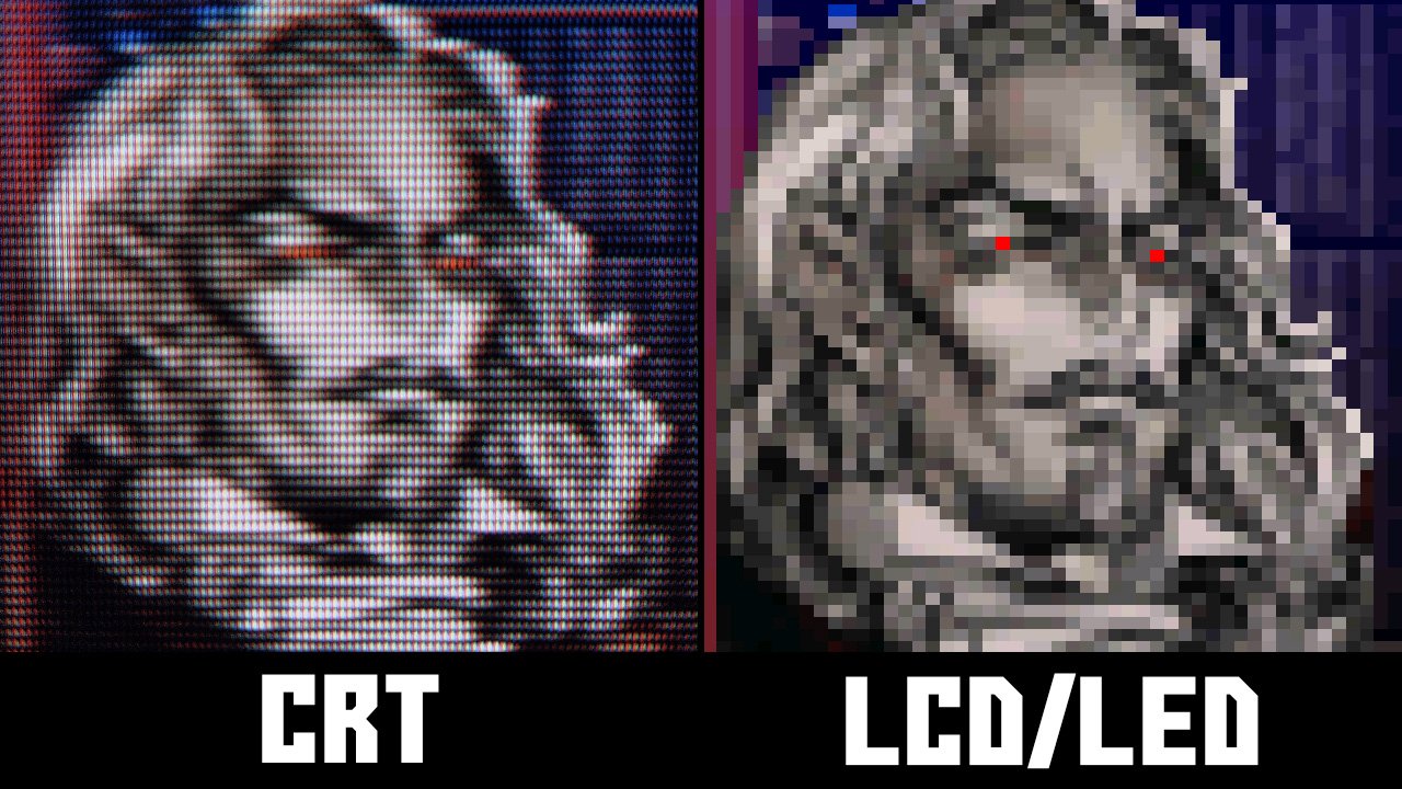
Next update will include proper brightness readings from my Trinitron, real world “R-G-B color brightness weight” and proper exponential brightness function (that took me some hours of calculating).
Added options to control each color “scanline weight” (how intense will be scanlines on blue, red, etc) and a CRT VGA mask inspired by an old post from Nesguy. I have to sort all those masks that I did and decide which to keep. What a mess lol
Ight, that scanline shit is fancy. That’s all I wanted to add!
New version that i promised with “rgb color scanline weight control”, some new masks (like CRT VGA) and glow on modified guest.r shader (which btw looks incredible now with all the changes).
https://mega.nz/file/ezwURZKY#WFzH2BSAAVLDUKcIMU4M2_m9XXJlu44y82DK-oYvi_M
Looking over the new update, stuff looks awesome!
Could you possibly send me a copy of that older guest version (without mods, for code comparison; sanity check  )?
)?
Regardless, cool work, I’m really digging the RGB scanline separation.
Sure, old version here, 1st post or 2nd.
http://eab.abime.net/showthread.php?t=95969
Regarding RGB separation, brightness relationship on my Trinitron is around 1 red, 8 green, 1 blue. But I prefer something more rounded with not so much difference. Green is super bright there.
So you’ve been keeping the red and blue scanline weights level, while “multiplying” greens weigh by 8?
No I prefer something like 2-3-1 relationship because if I use 1-8-1 the LCDs are not bright enough and it kills brightness on red and blue (full dark scanlines not taking into account how bright is red or blue). But there is no any problem on CRT because it’s super bright anyway.
Full green there is around 4 times more bright than full red and blue (magenta). If I use 4 times less bright magenta on LCD it will absolutely destroy any brightness left.
So is there a reason you’re applying the mask before the scanlines? (Or am I reading that code wrong?)
Just seems more common to go scanlines and then mask, instead of mask and then scanlines like you did.
Just curious. (Didn’t know if there was a logical reasoning behind it, or that’s just where it looked good  )
)
Both shaders do scanlines first, if you look the code. CRT-beam keeps a copy of screen named as mcolor and in the end of main() it applies the effect on that copy (that is before mask was applied).
Guest.r version does an “sw” function that does the scanlines taking in to account luma too. Both before mask.
I was reading your CRT beam shader wrong, carry on! 
Can you hand hold me through this? (Because my head is still saying you’re doing it the other way around in your CRT beam shader, as having a hard time wrapping my head around how it’s applying the scanlines before the mask.)
And as far as I can tell you’re using the mcolor tag to make a copy of the zfast blur, and then apply it as part of the glow, it also goes into the scanline weight (earlier), but I don’t see where it touches the mask command/tag anywhere.
As to ME it looks like you’re applying the zfast blur, then brightness, then white point (if on), fake gamma (if on), then mask (if on), gamma out (if on), glow/color boost (if on), scanlines, contrast (if on), saturation(if on). (Please, please, please, correct me if I’m wrong, I do want to learn, not trying to nitpick.)
vec4 screen = COMPAT_TEXTURE(Source, p);
The screen is read
vec3 mcolor = vec3 (screen.r,screen.g ,screen.b);
A copy of screen is saved to vector 3 mcolor (XYZ, RGB or whatever).
float scanLineWeight = CalcScanLine(f.y, mcolor);
The scanline is calculated with y coordinates of f.y and reading color values stored in mcolor.
Then at the end it returns a value based on the luminance of the colors of the mcolor, without caring about the mask and simply multiply the vector then.
Ohhhh, it’s more fundamental shader stuff I don’t understand  . (Seriously thanks for your time tho, going to go try and wrap my head around that.)
But it’s true that mask doesn’t affect scanlines, indeed it’s the other way around, scanlines affect the mask even if not caring what it did to image. Actually in reality on a CRT there is no scanlines it’s just a mask 
The proper shader would be
Read how many times we scale the source image. Let’s say 4 times. Texturesize/InputSize?
Read the simulated color r.g.b .
Decide the luminance
Divide luminance / how many times we scaled. If 4 it’s 0.25 steps. If luminance 0.75 draw 3 vertical lines, leave 1 black.
Read r.g.b values and draw vertical if R is 0.33 one dot, if G is 0.66 2 dots etc.
The CRT way

PS and then discover lcd luminance won’t cut it lol
A new shader i did, observing some screenshots of consumer CRTs like this. It uses a blur filter that can also take out dithering (Megadrive, ZX Spectrum etc) 
PS just tested, needs #define SAMPLES 20.0 instead of 20 to compile on my Android. Will fix in a later upload
DOWNLOAD
https://mega.nz/file/OypiHToa#V2h2qVBgDn_IVmk-Lg-uodvTgwEqs6Rte5rkSE24PYw
An update with fixed saturation and the Android problem too. Plus!, one tweaked version of CRT-Nes-Mini with z-fast filter, CGWG and Lottes 2 mask (RGB), saturation, blah blah etc that should display DOS VGA games properly. That should work well on 4x and 6x resolutions that i checked, but not well on 5x (scanlines not align well). If someone more experienced could help would be nice.
DOWNLOAD
https://mega.nz/file/zngl0CiY#OEylcd61QMCUFXrgBFMuXYIhbpXB7GfuY48OYsFL3vU
Updated consumer-crt with curvature, glow, corner and replaced the crappy scanline code that wouldn’t scale properly on 5x with superior guest.r scanline code that scales well on any scale or non-integer (screens non integer).
I will settle with the changes and then pass a PR to github or hunterk will go crazy with the commits 
DOWNLOAD https://mega.nz/file/L2gxUQjQ#zuObX6CwMRi9W9A71PSPgyRiobIplY3uzHuiwl6dXOs


