I am working on a revised version with composite and resolution controls. Will post glsl/slang here when it’s done. Or if you prefer s-video will do that too.


I am working on a revised version with composite and resolution controls. Will post glsl/slang here when it’s done. Or if you prefer s-video will do that too.
Not rushing but bring all you can. Composite, S-Video, the console specific stuff you were talking about earlier.
Once it’s packaged and ready, I’d probably try to swap out the decoupled CRT-Guest-Advanced-NTSC section in my current stack (I’ll loose afterglow and the horizontal filtering section) and have a play around.
For the most part, I’m pretty satisfied with what I have done in my last 2 preset packs but I don’t mind playing around with the new stuff.
Display Brightness/Quality and motion clarity are the next areas I would hope to see improved because I did get a taste of it and it was good but brightness and overall image quality took a step back.
I’m wondering if we should also be looking into TV’s/display’s with lower sample and hold times in addition to things like BFI and strobing and stuff.
GLSL 1st version here, will follow with SLANG (hate those #define params. crap)
EDIT: There you are with SLANG too.
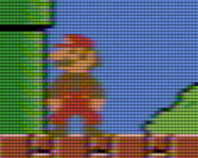
Some demonstration, artifacts roll in realtime and not so visible. Tuning the glsl and later transfer to slang. This is true composite mod/demod and everything.
Taking in to account that RF is blurrier and huge interference usually and s-video is sharper with minimal dot crawl (it just solves itself if chroma is separated on shader without me doing anything tricky).
Composite look
S-video
RF
Actually love the s-video look for everyday use, if interested i can make a light true s-video “module” shader that you can plug as a previous pass to any shader.
can you please post the preset parameters for each one of the screenshot looks / modes ?
Also, is there some way to fix the position for rainbow bands ? It look like diagonal rainbow is adapted for NES, as far as I know.
I have a 35 years old NES with RF so i know that diagonal look is for that console.
Also, I looked for Dust/Noise and does not seem to bring any interference.
Thank you again for sharing
Looks great but all TVs would have applied some kind of sharpening (maybe not the bargain brand Walmart TV) - what’s your preferred sharpening method?
Still working on it on NES/SNES mode, i added some default modes for RF/composite/s-video. These screenshots are using that modes, while resolution controls still work. In the meantime you can test ntsc-mini i wrote in MD mode and tell me what you think of it.
Any info (and evidence) how TVs applied sharpening? No need to add sharpening lol, there is a switch to deteriorate the image at will from default super-sharp LCD that’s already there.
Before reaching the screen, the video input signal from your game console goes through several stages in the CRT’s video processing circuits. One of those processing circuits is called amplification, where it takes the low voltage video signal from your console and boosts it into a level that the CRT can better work with. During this amplification process, some of the higher-frequency details of the signal are lost. The details in these higher frequency portions of the signal are all the sharp edges that should be on things like text and sprites in your games. How much detail is lost depends on the quality of the video amplifier circuit, but there is a baseline of loss that is naturally unavoidable.
TV engineers noticed this and tried to develop a solution to counteract it. They added a processing stage called “sharpness” that attempts to over-emphasize the high frequency portion of the signal before amplification to try and mitigate how much detail is lost.
The sharpness adjustment on your TV increases the video amp gain for the higher frequency parts of the signal (i.e. the edges). The higher frequency parts of the signal often fall off during amplification due to technical limitations - so increasing sharpness in the TV menu amplifies the high frequency section of the signal to try and balance the loss.
This is new for me. I never considered something like this was happening. I’m guessing this has to do specifically with RF demodulation. Otherwise, it could have to do with every input the TV has.
Up to this point, I believed sharpness was just about Y separation, setting a trade-off in how much chroma interference the user can tolerate in luma. Lower sharpness leaves you with just the lower 2 MHz that’s almost entirely luma, and higher sharpness includes higher frequencies which do include luma but also contain ripples from chroma. Higher sharpness also just inherently increases ripples even if the image is in black and white.
Even when I coded an adaptive comb filter, I found myself adding in a sharpness control for it because I thought it looked better.
Hearing that it’s about a voltage amplification circuit is interesting.
I need to check more of these datasheets, but the ones I’ve looked at seem to agree that sharpness is applied specifically to the Y signal without affecting C, and that Y/C separation is handled separately from the chip, before the chip is ever reached, which might mean doing simple bandpass and bandstop filters with inductors and capacitors, or using a separate dedicated comb filter chip. An exception is the CXA2025AS which has a built in notch filter that can be toggled.
For some reason, my Panasonic TV from 2000 also applies sharpness on s-video and component signals. I assume it’s to save cost by reusing components.
My Toshiba FST Blackstripe CF2005 from 1985 seems to lack a sharpening circuit, or at least a sharpness dial. The 1989 RCA ColorTrak Remote does have sharpness though, and I should mention this TV has an on-screen display, unlike the Blackstripe.
first image is from v0.2 update. It now does not show diagonal lines but instead some small colorful dots
Second is NTSC-mini. I think would be a bit more handful here to control “Color Clock Frequency Mhz” parameter with smaller values. I know here it alternates between different values but I cannot control distance between rainbow lines with more accuracy like other ntsc shaders do around, already. Just my little opinion.
ntsc-mini has a “custom” mode that you can change whatever you want as long as you can provide the proper phases. Default MD mode is exactly where it should be though. As for the ntsc shader we are about it’s still in progress, problem is that if i add comb etc with number of passes it potentially does (like e.g. Q resolution 20 will do like 32 passes alone, add another 16 passes for I and a bunch of passes for Y, consider that it will do a ton of calculations on each pass-as this is true composite mod/de-mod) will crawl even on very powerful PCs.
It’s there on latest SLANG/GLSL if you update your shaders.
oh, there we go. Thank you a lot !
Definetely good job from you. Really amazing.
The only thing is that could not control the amount of Dithering with ntsc mini. Is adviced any other shader in that case to combine with it? Thank you again
This is new for me. I never considered something like this was happening. I’m guessing this has to do specifically with RF demodulation. Otherwise, it could have to do with every input the TV has.
Amplifiers can act like a low pass filter because of their slew rate. The amplifiers feeding the electron guns probably had the strictest slew rate requirements because the voltages were relatively high. Ideally, amplifiers would be chosen so that the slew rate is not a limiting factor.
I don’t know how often this was an issue in CRTs, but I suspect that the main reason manufacturers started adding sharpening circuits is just that people preferred the look. TVs still have sharpening controls today despite being able to display a pixel-perfect digital image.
For some reason, my Panasonic TV from 2000 also applies sharpness on s-video and component signals.
My JVC D-Series also applies sharpening to the component input.
Meanwhile i got bored of that single pass shader, gutted some of the previous work, tweaked the ntsc to be more accurate, and injected to this. It’s a real mod / de-mod / s-video as usual and consumes 1.6 watt on my HD630 laptop (zfast-crt is 1.2, gtu-v50 will top ~10 watt). Pretty damn good for what it offers. If any interest i’ll port it to SLANG too.
real composite
svideo
MD mode
NES artifacts test
hi, please Slang version. Thank you for your work!
Composite video as seen on a TV is much sharper than that thanks to the TV’s sharpening circuit. I’d say that’s the next step. Keep up the good work!
Ok so i added an adjustable “Sharpness” switch, more or less how a window function would average texture fetches and preserve higher frequencies (sharp edges). That costed 0.2 watt lol, now it’s up to 1.8.
before (you can zero the sharpness and go back to this), it was more like RF sharpness
after (that’s closer to my RPI 2W sharpness on Composite)
First settle GLSL and then i’ll port the final version to SLANG.
a simple way to precalculate 2 texture fetches and a window function, one fetch at 0.5*1.0/TextureSize.x distance and one at 1.5 and get the values. I just used one out of my head and works just fine.


