Configuring guest.r's scanline-mask shader for a 500 nit display

Just playing around, trying to configure @guest.r’s scanline-mask shader for a 500 nit display using my iPhone 6 screen. My goal is to max out the mask strength while maintaining adequate brightness, contrast and color. Maximum mask strength is required for accurate CRT phosphor emulation, with the phosphors displaying accurate RGB intensity values.

Final(?) edit (1/16/2020):

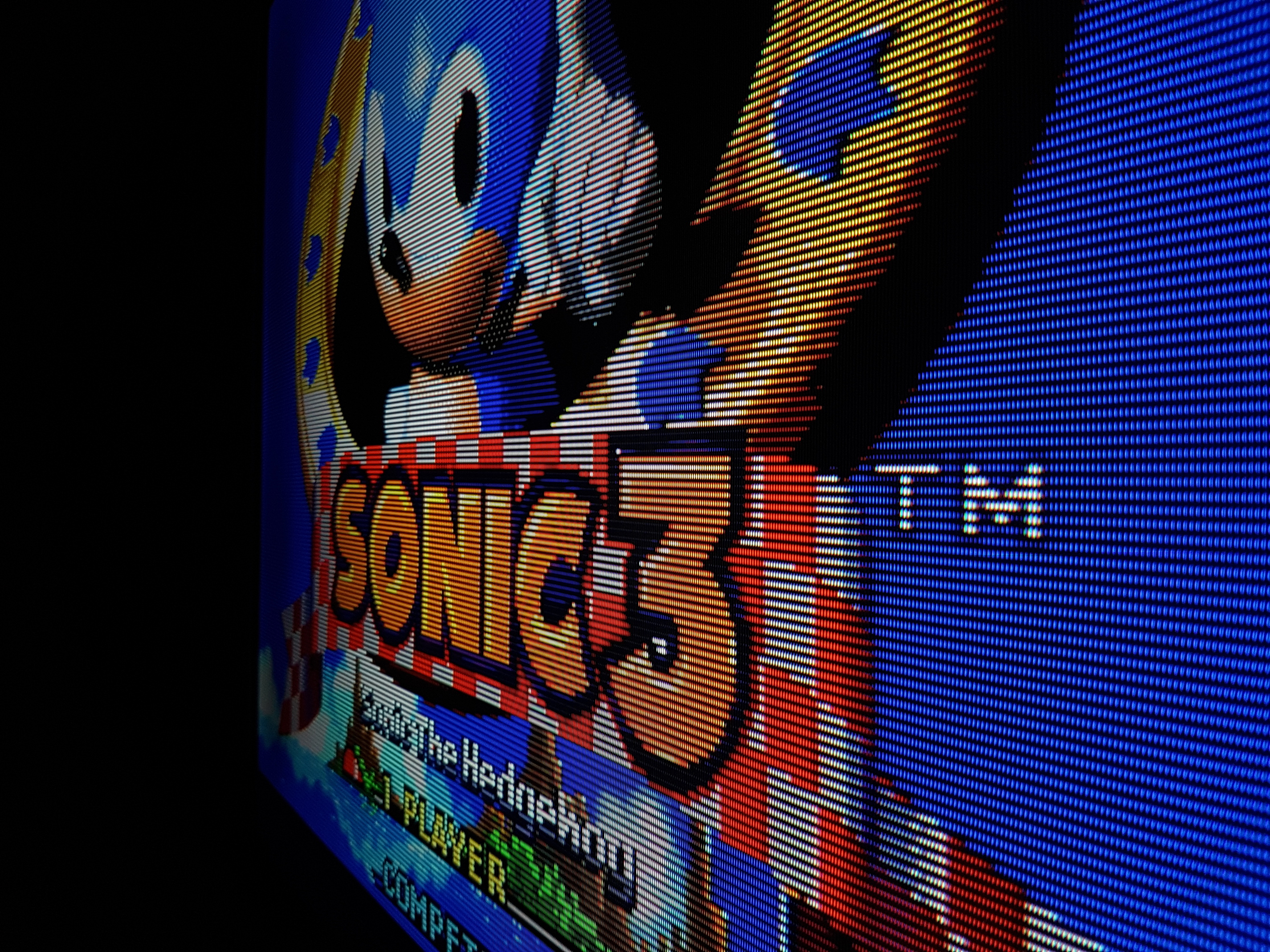
@guest.r I’d welcome any feedback/tips here. See the photo of Sonic 3 on the KV310 for reference :slight_smile:

These must be viewed full size on a 1080p display and you need a display with a max brightness of 500+ nits with the backlight cranked up to 100%. If these aren’t viewed full size at 1080p then the mask/scanlines get scaled in a way that makes the images a lot darker. If you don’t have a display with 500+ nits, the images will be unacceptably dark. For 350+ nit displays (most LED-lit LCDs), check out these settings.

Overall, I really like what I’m seeing regarding scanline shape and variation! Compare the screenshot of Sonic 3 to the photo of Sonic 3 on a Sony FV310.

“Max backlight” settings for a 500+ nit display:

 -scanline edges at max
-scanline center at max
-gamma at 3.00
-crt mask dark at 1.00
-crt mask bright at 1.00

inner bars should be just barely visible in a dark room:

2 Likes

Mini off topic, but I’m sure it will interest you :stuck_out_tongue:

https://www.anandtech.com/show/15174/japan-display-develops-16inch-micro-led-display-module-265-ppi-3000-nits

Micro LED technology is a promising candidate for higher-end displays and television that will be available three to four years down the road. The technology has virtually all the quality advantages that OLED has to offer (over LCD), including individually-controlled LEDs, high contrast, fast response times, and wide viewing angles. But equally important, it does not come with the major disadvantages that OLEDs are known for, such as off-axis color shifting and aging-related burn-in.

1 Like

test

EDIT2: still doesn’t look quite right to me. Too much bloom and not quite bright enough. See first post for updated settings.

1 Like

New screen looks pretty good to me, cracking my phone brightness all the way.

I think it would benefit from very, very, slight blurring, and possibly the tiniest touch of halation/diffusion (that second is more a personal preference but I do think it could look really nice if done right.)

Regardless, nice screens.

1 Like

lol, was just about to delete that one :laughing:

I’m not liking the amount of bloom I’m seeing in the previous shot. This is pretty much what I’m going for:

This is a Sony Wega FV310. It’s a consumer-grade CRT television from the mid 2000s. It’s basically the best consumer CRT you can get. What sets it apart from other CRT TVs is the high voltage regulator that eliminates bloom, color bleed and other picture distortions. As you can see in the photo, the scanlines are quite sharp and well-defined, especially for a consumer-grade CRT, but the mask structure is still visible. It sits somewhere between a PVM and a regular Sony Wega in terms of picture quality.

The difficulty with recreating this with shaders is that you simply don’t have sufficient brightness on most LED-lit LCDs to compensate for both the scanlines AND the mask without doing weird stuff to the colors. In fact, 500 nits is probably barely sufficient for this sort of thing, and you probably want more like 600 nits. If you want to do BFI on top of that, you’re looking at 1000-1200 nits(!)

Here’s where I’m at right now; these are settings for my normal display (~350 nits). Changes from the defaults:

-scanline edges at max
-scanline center at max
-gamma at 2.70
-crt mask dark at 1.00
-crt mask bright at 0.70

Example of current settings for ~350 nits:

new test, settings for 500+ nits:

This is with scanline center/edges both at max, mask light/dark both at 1.00, gamma at 3.00, everything else default.

1 Like

@guest.r

Any tips/tricks you can offer, here? The goal is to max out the scanlines/mask while keeping brightness, contrast and saturation intact. Obviously, a very bright display is required for this to work (at least 500 nits).

My method thus far:

  1. Max out display backlight
  2. Max out scanline center and scanline edges
  3. Max out gamma correction (3.00)
  4. Set mask dark to 1.00 and set mask bright as high as possible while still being able to barely the see the inner bars of the PLUGE test pattern (using Fudoh’s 240p test suite).
1 Like

Using a zero/one mask strength (in other words, maxed out masks) really demands a good display and shader settings do a poor job to compensate on an average monitor.

Maybe some sort of bloom effect would help as bright pixels would distribute themselves over the image and the overall look would be brighter.

It seems like most of the things you can do to the image through software to compensate for lost brightness just wind up compromising the image in other ways. Luckily, much brighter displays are on the horizon!

It could help with brightness but I think it would have a detrimental effect on contrast and saturation, and lack of saturation is already a problem for an sRGB display trying to emulate an NTSC CRT… it could be a nice tool to have for those with wide color gamut displays, though.