Hi!
I’ve generally used crt-lottes, crt-lottes-fast, or occasionally crt-royale. I have also been interested in the ideas behind GTU, though I thought it never quite looked right (more on that later). With that in mind, I thought it would be interesting to write my own shader.
This shader has a similar format to GTU.
The first pass transforms the color space to CRT gamma (and optionally to YIQ for simulating composite). The input is assumed to be sRGB. This may or may not actually be the case. I assume some cores output in simple 2.2 gamma and some might output in the original system gamma, but I haven’t looked at the code to check.
The second pass low-pass filters the signal to simulate the bandwidth limitations of analog video. This uses a continuous-time FIR filter with a raised cosine kernel. After I sat down and did the math, I realized this was the same way GTU does its filtering. I think the only real difference here is that the filtering happens in the CRT gamma space (in either RGB or YIQ), and then the result is transformed to linear RGB. The output is a series of samples from the band-limited signal.
I should note that, like in GTU, this is not a full NTSC simulation with the “Composite” parameter turned on. The bandwidth limitations are simulated without the effects of trying to separate the chroma from the luma. In this way it is really more like S-Video (or a very good comb filter) and won’t result in dot crawl or color fringing artifacts. With a little work, it is probably possible to replace the first 2 passes with the ntsc-adaptive shader for truer NTSC composite simulation.
The third pass draws scanlines. One easily visible difference here is that the scanlines are drawn and blended in linear RGB space. Many other shaders seem to do this (e.g. the lottes shaders), but GTU handles scanlines in gamma space. I believe this is part of why I find that GTU looks a little “off.”
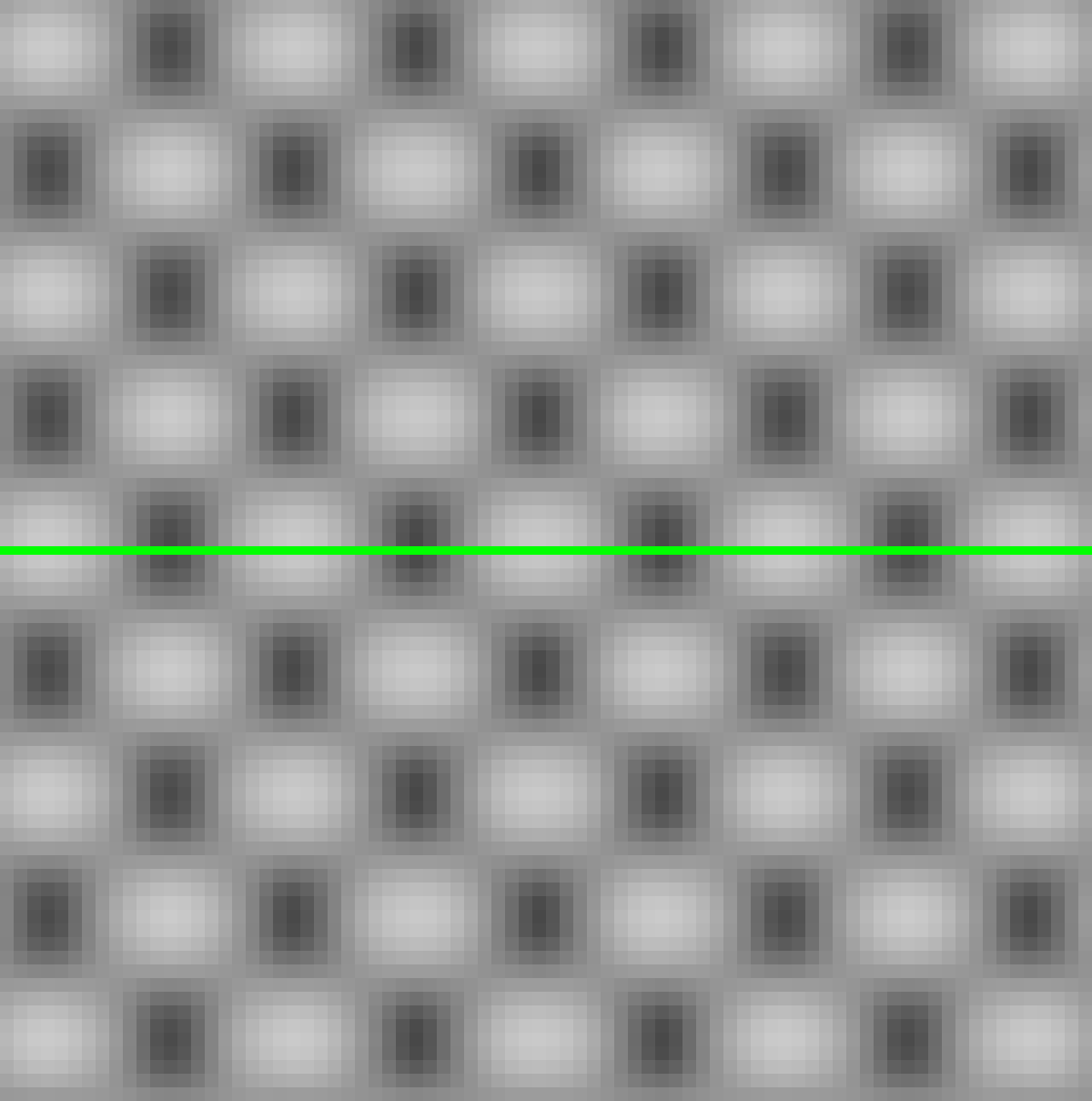
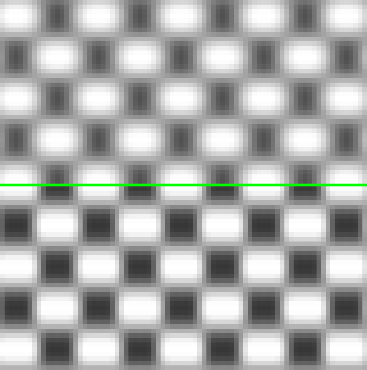
The scanline handling is also completely different. The way scanlines are drawn is by simulating the scanning of a roughly circular spot (or really three, one for each color) across the screen, varying in brightness and width according to the band-limited input signal. In other words, the same way CRTs work! There are some simplifications for mathematical convenience and in pursuit of my other goals. I think this is one of the most interesting parts of the shader, and I will try to explain the math later.
The system requirements are higher than something like crt-easymode, and probably a bit lower than something like crt-royale or crt-guest. There is a lot more math in the scanline simulation than some of the faster shaders. It runs easily in 4k on my RX 5500 XT. This is the first shader I have ever written, and there is probably some space for performance improvements. To be honest, I’m not sure how to go about profiling a shader, which is how I would normally start performance optimization.
I had a few goals in developing this shader:
-
Approximate brightness preservation As long as the maximum spot size is 1.0, the image overall should not be significantly darker than the input image. Thinner scanlines in darker areas are brighter at their peak to make up for the brightness lost in the dark areas between them (as I believe they would be on a real CRT). There are no “tricks” to boost the brightness like raising the midtones, which would alter the tonality of the image.
Lower values for the maximum spot size will result in darkening proportional to the value chosen.
-
Consistent sharpness regardless of horizontal input resolution Some shaders get much sharper when the horizontal resolution of the input increases. This shader retains a consistent sharpness. For example, imagine stretching a 256 pixel wide input image to 512 pixels by duplicating every pixel horizontally. The output should look exactly the same.
CRTs did not have pixels (as I’m sure everyone in this forum is aware), and sharpness was dictated only by the bandwidth of the signal, the size of the spot, and the pitch of the mask.
This is especially important for systems that have multiple output resolutions, or games that switch resolutions for different screens (e.g. menus and cut scenes). This way the settings can be set once and a consistent look can be achieved.
-
No clipping There should be no clipping of pixel values beyond minor floating point errors or possibly out-of-gamut colors from the YIQ to RGB transform. The filter has no negative lobes and the scanline simulation should not result in values above 1.0.
This should help preserve the tonality of the image. Highlights and shadows should not be lost.
-
Simple, limited parameters I wanted something that was easily customizable but not overwhelming. Hopefully that is what I ended up with!
Parameters
-
Composite Uses the NTSC YIQ color space for filtering when set to 1.0, and RGB otherwise.
-
RGB/Y bandwidth (MHz), I bandwidth (MHz), and Q bandwidth (MHz) The -6dB cutoff frequencies of each signal component. Between 4 to 6 MHz seems about right for RGB bandwidth. Y bandwidth for S-Video would be similar. Y bandwidth for composite would vary depending on the quality of the filter in the television and the quality of the source (the Mega Drive/Genesis had a notoriously poor composite output). I and Q bandwidth should probably be around 0.6 MHz. Technically, I bandwidth should be limited to 1.6 MHz, but in practice it seems that most televisions disregarded the extra bandwidth because it would require an extra filter and delay lines to implement proper filtering. Composite connections might theoretically be allowed to use 1.6 MHz for each of I and Q (see SMPTE 170M), but I’m not sure if any systems or televisions used that outside of studio applications.
-
Maximum spot size The maximum size of the CRT spot, relative to the scanline height. A setting of 1.0 will completely merge scanlines at full brightness.
-
Minimum spot size The minimum size of the CRT spot, relative to the maximum size. A setting of 1.0 will result in scanlines that do not vary with brightness of the signal. If the maximum and minimum are both set to 1.0, all scanlines will be merged.
-
Samples per line This isn’t an actual exposed parameter, but you can see the value in the
scale_x1field in the slangp file. This is the number of samples generated by the output of the filter pass. Values that are too low (i.e. below Nyquist plus some headroom for filter rolloff) will result in aliasing and degrade the output. This also dictates the number of samples that can be used to estimate the integral in the scanline pass, so higher values will result in a better estimation. Values that are very high will impact performance by requiring more executions in the filter pass and more iterations in the scanline pass.I ran a quick experiment and found that values between 900 and 950 performed well (generally requiring only 7 iterations in the scanline pass) and also looked good. When comparing against outputs created with 2880 samples, PSNR was over 50 dB and the SSIMULACRA2 score was around 100. I don’t think anybody will notice a difference in normal use. The image really starts to degrade below 800 or so.
The odd value of 907 is my (probably misguided) attempt to avoid something like interference patterns by picking a prime number.
Future improvements
If there is interest, here are some things I would like to add, roughly in the order that I would probably implement them:
-
Interlacing support This is especially important for games that switch between progressive and interlaced for menus or cut scenes. Currently interlaced content won’t look correct. When the vertical resolution is higher, it will just look like there are more, smaller scanlines.
-
Overscan Some games and systems rendered garbage in the overscan area and it would be nice to be able to cut that off.
-
Curvature I need to think through the math on this.
-
Glow The glow around bright areas of the screen as the light passes through the CRT glass. I believe this can be done fairly efficiently as a separable gaussian blur using mipmaps. Someone has probably done this already in another shader.
-
Mask simulation I have this last because I have not been happy with most approaches. In other shaders, I often just turn mask simulation off when I can.
The subpixel masks are difficult to configure, get vastly different results on different display resolutions, won’t work on some displays, and greatly affect brightness. I would like a particular shader configuration to look consistent across all display types.
Tiling a mask texture across the screen and resizing can achieve consistency, but doesn’t work well at low resolutions and still requires tricks to boost the brightness back up.
Still, I think mask simulation is important. I’ve been curious how it is done in the koko-aio shader but have not dug into that yet.
Things I’m not really interested in adding (unless convinced otherwise):
-
Simulating flaws or misconfiguration, such as deconvergence, raised black levels, poor focus at the screen edges, etc. I know CRTs often had these issues, but I don’t personally feel like they are important for replicating the experience. I would rather simulate an ideal, properly configured CRT. Besides, these sorts of things can really blow up the parameter count.
-
Simulating the color space of the CRT phosphors Mostly, I think this is too inaccurate in the sRGB color space (which I am targeting) because you will have to deal with clipping or mapping the colors into the gamut. It would probably be more practical on an HDR display with DCI-P3 or Rec 2020 coverage. In any case, the sRGB primaries are relatively close to the SMPTE C and EBU primaries. Considering the disregard most CRT televisions seem to have had for standardized color, I consider it close enough.
-
Temporal effects like ghosting due to phosphor persistence I don’t think that phosphor decay time was long enough to bleed into the next frame, at least on later CRTs. See the Slow Mo Guys’ videos of CRTs.
Screenshots
Anyway, sorry for writing so much above. Here are some screenshots!
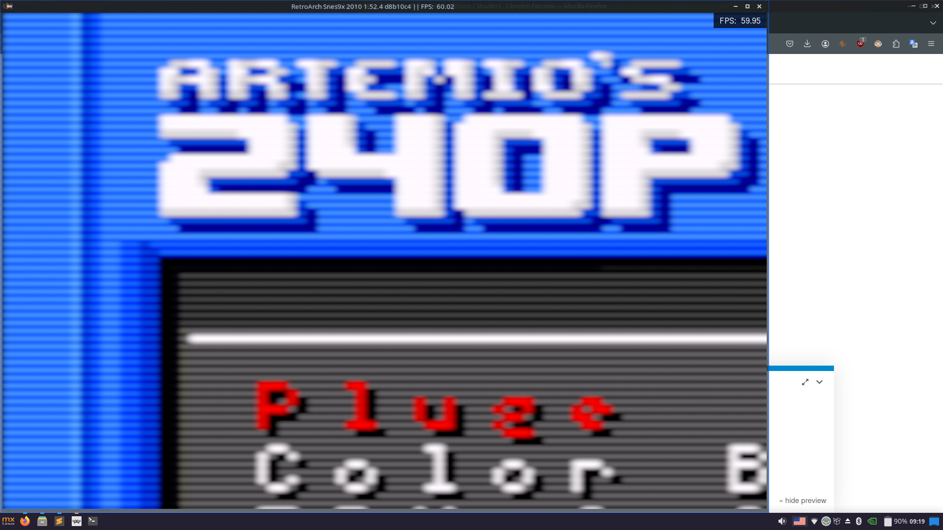
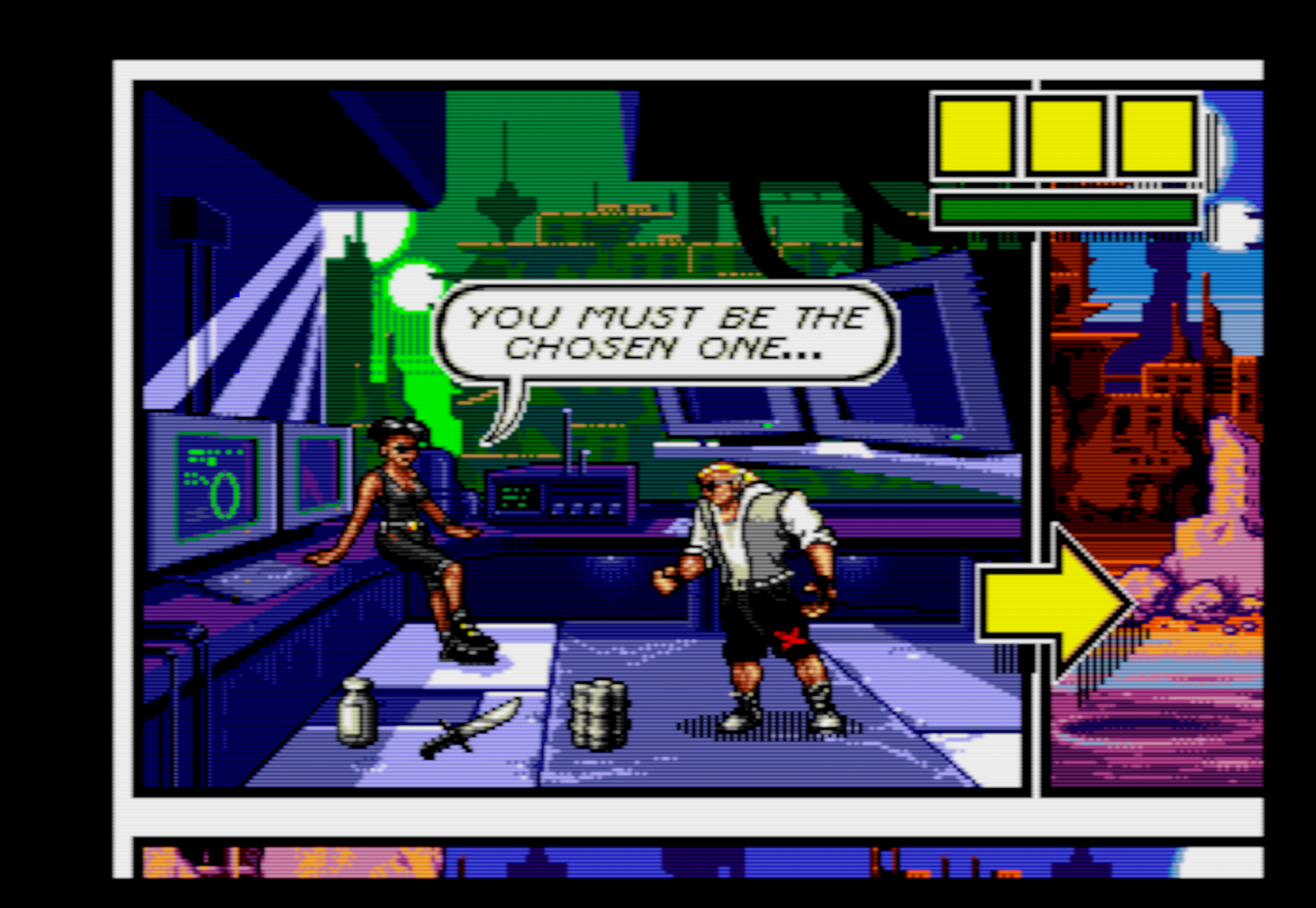
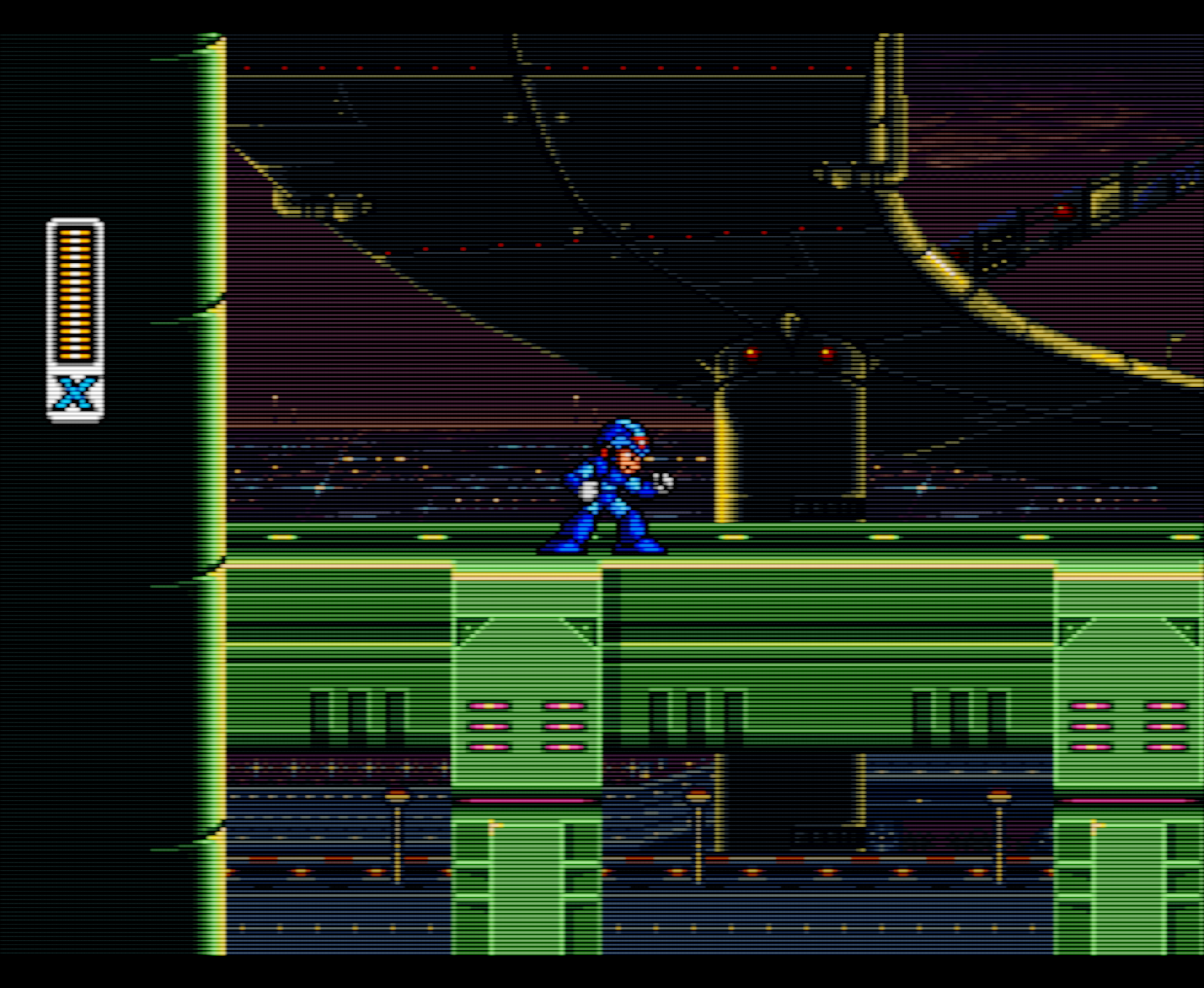
Simulating a decent, late model CRT connected with component or RGB:
Composite = 0.0
RGB/Y bandwidth (MHz) = 5.0
I bandwidth (MHz) = 0.6
Q Bandwidth (MHz) = 0.6
Maximum spot size = 1.0
Minimum spot size = 0.5


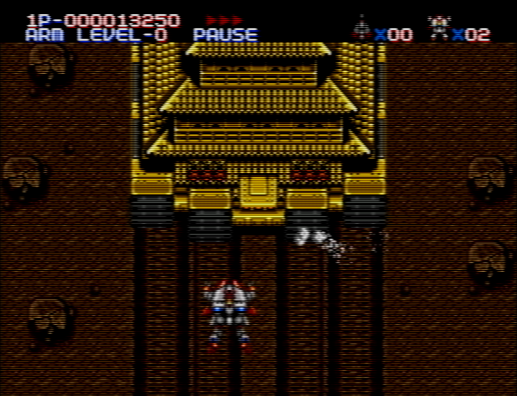
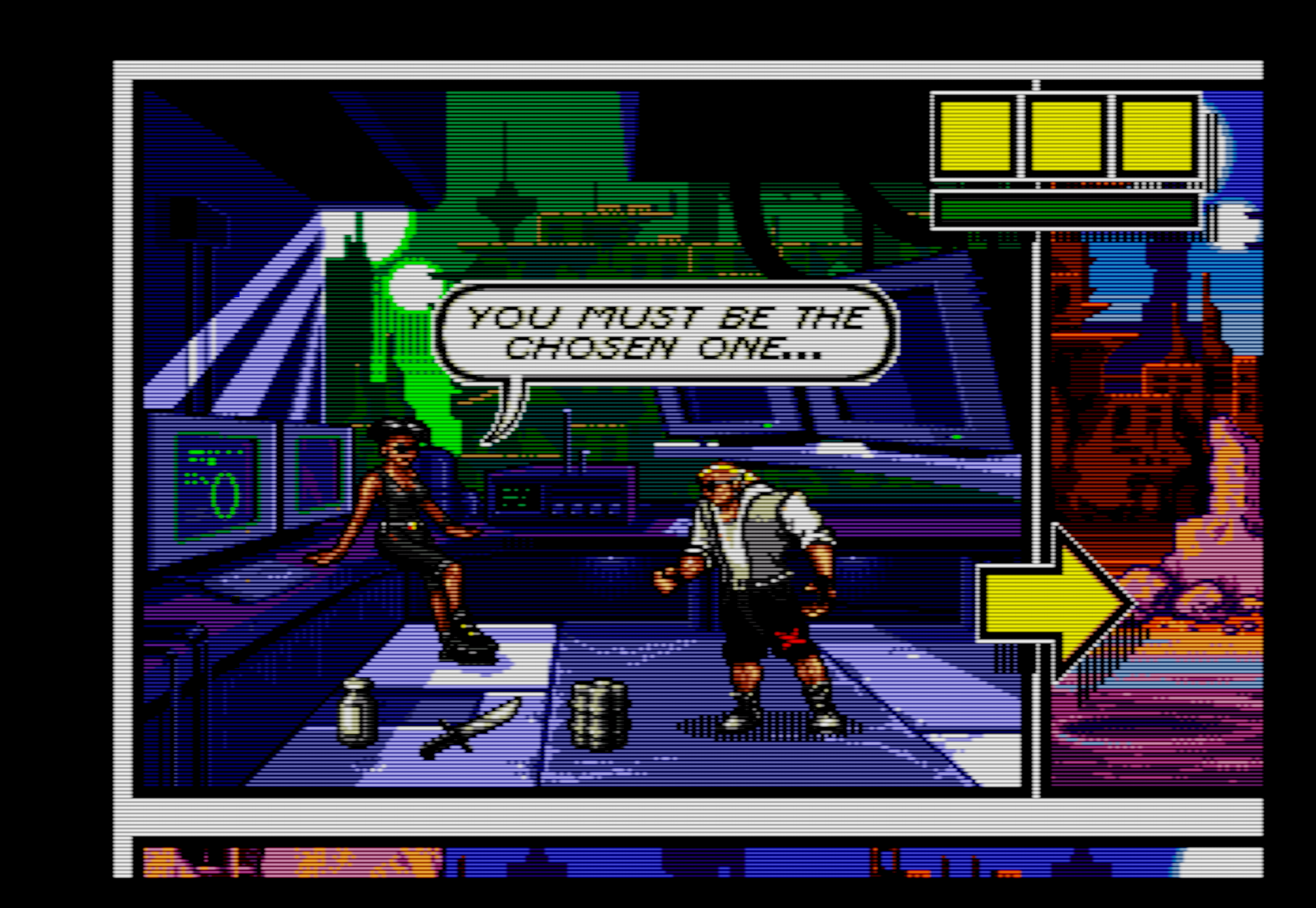
Simulating a similar CRT, but through terrible Mega Drive/Genesis composite (notice the blending of the drop shadows):
Composite = 1.0
RGB/Y bandwidth (MHz) = 1.6
I bandwidth (MHz) = 0.6
Q Bandwidth (MHz) = 0.6
Maximum spot size = 1.0
Minimum spot size = 0.5


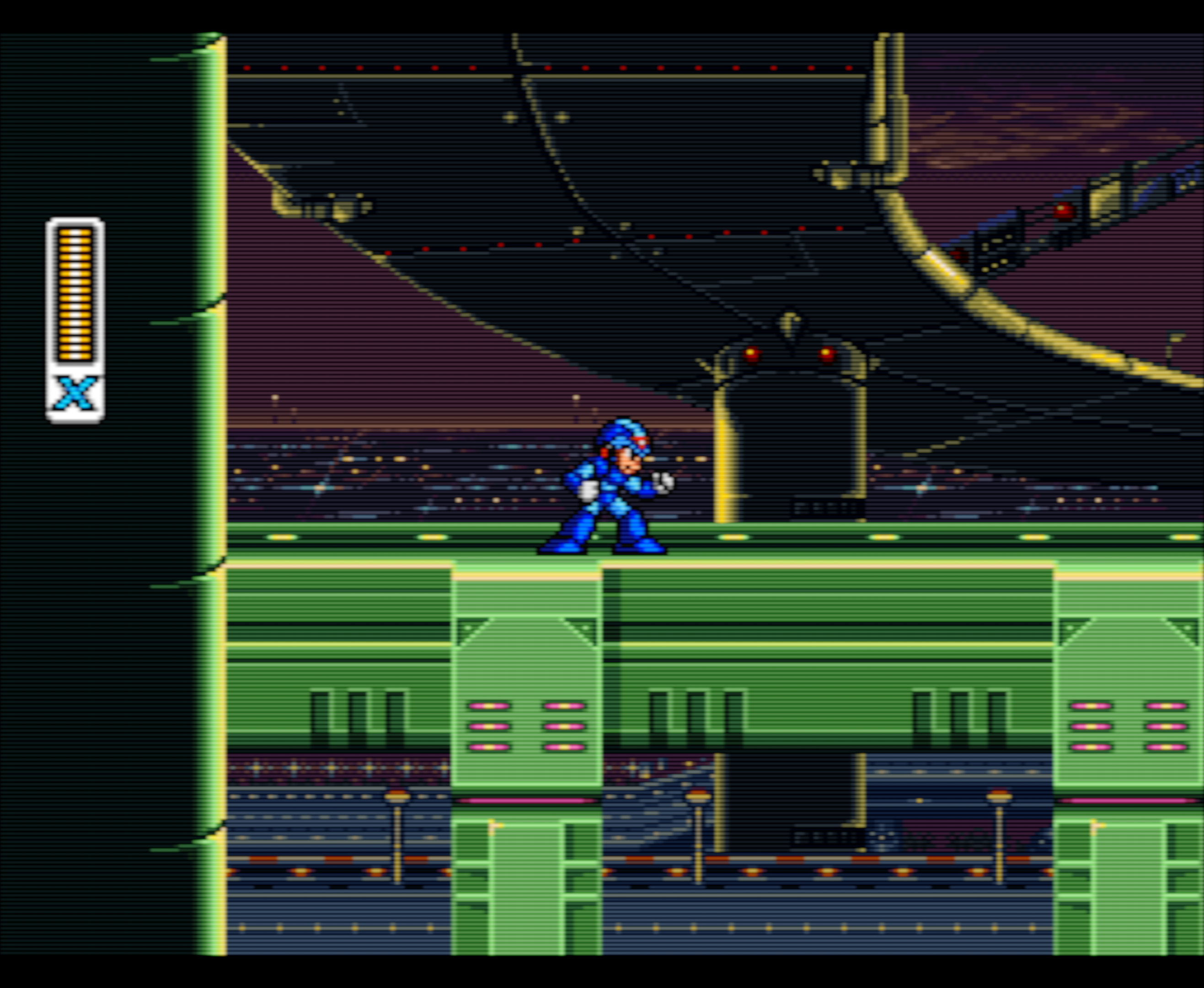
Simulating something with more pronounced scanlines, like a PVM or broadcast monitor, connected through RGB:
Composite = 0.0
RGB/Y bandwidth (MHz) = 5.0
I bandwidth (MHz) = 0.6
Q Bandwidth (MHz) = 0.6
Maximum spot size = 0.75
Minimum spot size = 0.3
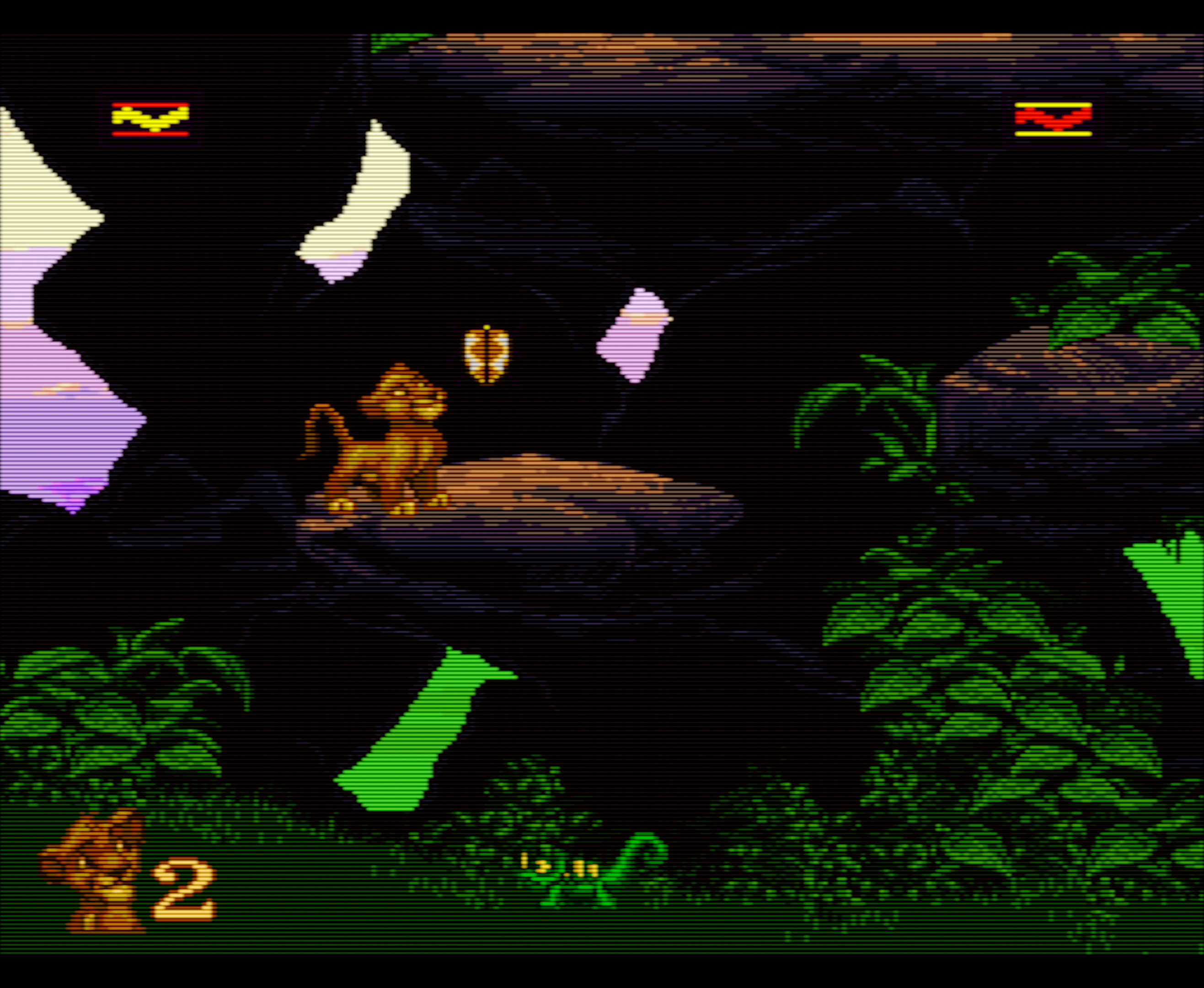

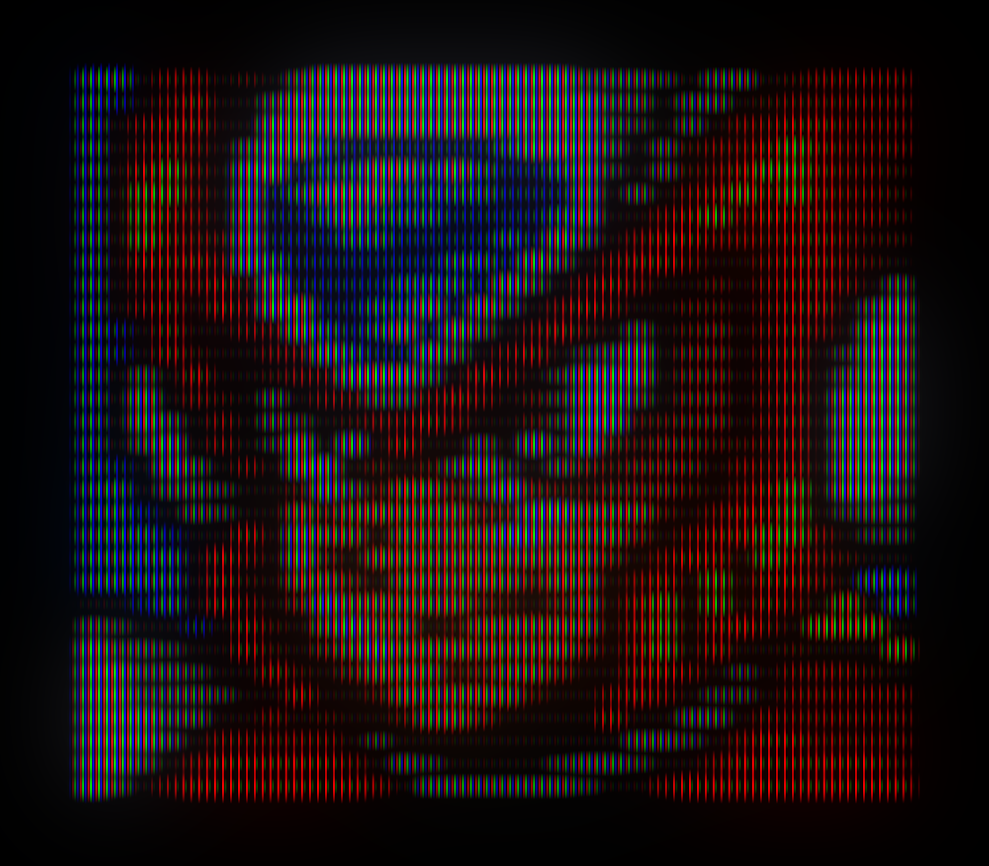
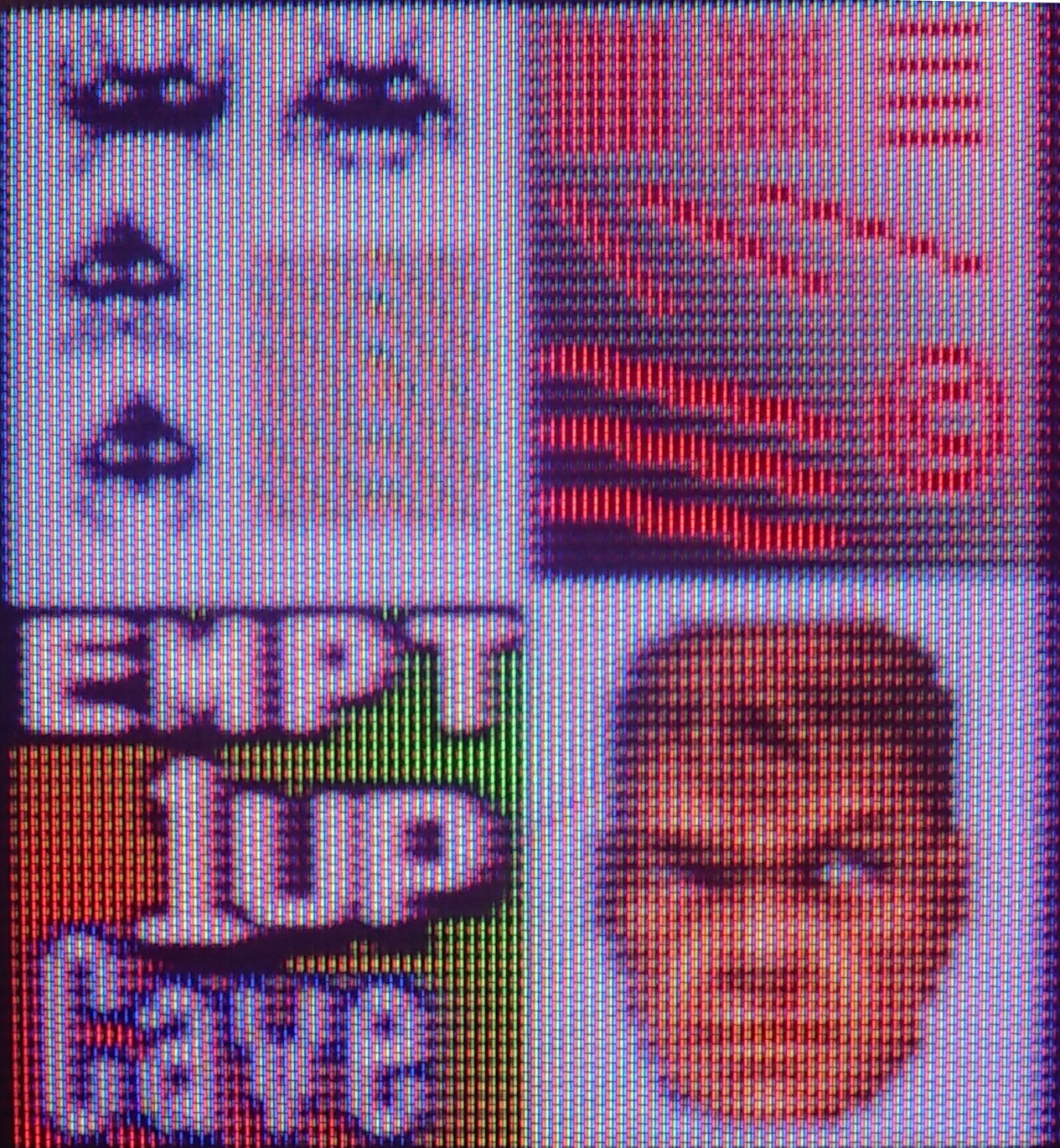
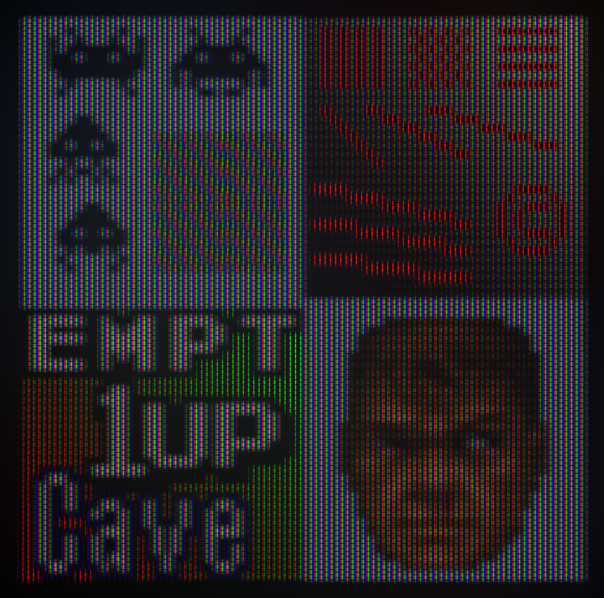
And for fun, here are some high resolution renderings using my Python proof of concept code, with masks overlaid: