Thanks @MajorPainTheCactus for further investigations.
Unfortunately the issue with the masks in DCI-P3 is not fixed.
Below is an extended testcase that dives into the interaction between color gamut mapping and mask quality. I’m sure this will convince you there’s an issue in the color gamut mapping and interaction with the masks.
The essence is that colour gamut mapping of 709 (or any smaller gamut than DCI-P3) to a wide gamut like DCI-P3 or 2020 is not doing any “true” primary conversion, but instead is just scaling the RGB values. This is the intended way color gamut mapping works I think, but for our use or because of the current shader (mask?) implementation it is having an adverse effect on mask quality unfortunately.
In fact I’m quite sure ANY color mapping of a less saturated space into a more saturated (i.e. wide gamut) space is negatively affecting mask quality in the current shader, which would include the HDR shaders, as mapping 709 to 2020 is their default.
I’ll let the results below speak for themselves. The essence of space “A” and “B” are that they’re the same as DCI-P3, except for the green primary: they are less saturated as pictured below. That way we can single out issues by only having to focus on the green channel.
To replicate my results please add the following three color matrices to “gamma_correct.h”:
// DCI-P3
const mat3 kDCIP3_to_XYZ = mat3(
0.4865709486f,	0.2656676932f,	0.1982172852f,
0.2289745641f,	0.6917385218f,	0.0792869141f,
0.0000000000f,	0.0451133819f,	1.0439443689f);

// DCI-P3 "A" -- Green primary changed to Gx=0.28, Gy=0.50
const mat3 kDCIP3A_to_XYZ = mat3(
0.3795617857f,	0.4279562091f,	0.1429379323f,
0.1786173109f,	0.7642075162f,	0.0571751729f,
0.0000000000f,	0.3362513071f,	0.7528064436f);

 // DCI-P3 "B" -- Green primary changed to Gx=0.30, Gy=0.40
const mat3 kDCIP3B_to_XYZ = mat3(
0.2190998562f,	0.6475197396f,	0.0838363312f,
0.1031058147f,	0.8633596528f,	0.0335345325f,
0.0000000000f,	0.6475197396f,	0.4415380111f);
and replace the “else” for the DCI-P3 conversion by this:
  else
  {
     //const vec3 dcip3_colour = (scanline_colour * k709_to_XYZ) * kXYZ_to_DCIP3;
     //const vec3 dcip3_colour = (scanline_colour * kDCIP3_to_XYZ) * kXYZ_to_DCIP3;
     //const vec3 dcip3_colour = (scanline_colour * kDCIP3A_to_XYZ) * kXYZ_to_DCIP3;
     const vec3 dcip3_colour = (scanline_colour * kDCIP3B_to_XYZ) * kXYZ_to_DCIP3;
     gamma_out = LinearToDCIP3(dcip3_colour);
As for the preset, I’ve used your default 2730-sdr preset and changed nothing EXCEPT for
- colour space to DCI-P3
- colour system to “0” (709), as the NTSC-J mapping is also causing adverse effect on mask output, although less noticable.
I’ve attached the preset with these two changes at the end.
So below are three results, first DCIP3 to DCIP3, then DCIP3A to DCIP3 and then DCIP3B to DCIP3.
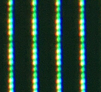
DCIP3 to DCIP3 – ALL OK since there’s no color scaling happening
 //const vec3 dcip3_colour = (scanline_colour * k709_to_XYZ) * kXYZ_to_DCIP3;
 const vec3 dcip3_colour = (scanline_colour * kDCIP3_to_XYZ) * kXYZ_to_DCIP3;
 //const vec3 dcip3_colour = (scanline_colour * kDCIP3A_to_XYZ) * kXYZ_to_DCIP3;
 //const vec3 dcip3_colour = (scanline_colour * kDCIP3B_to_XYZ) * kXYZ_to_DCIP3;
240p WHITE test screen
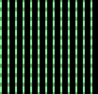
240p GREEN test screen
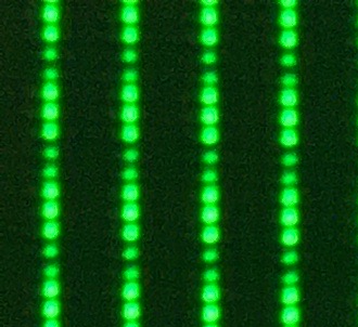
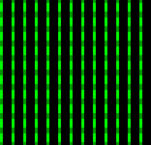
GPU snapshot of mask, note green is (0,255,0)
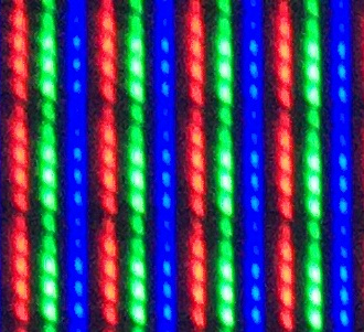
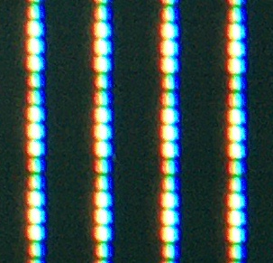
DCIP3A to DCIP3 - ISSUE, red and blue subpixels light up left and right of the green subpixel.
 //const vec3 dcip3_colour = (scanline_colour * k709_to_XYZ) * kXYZ_to_DCIP3;
 //const vec3 dcip3_colour = (scanline_colour * kDCIP3_to_XYZ) * kXYZ_to_DCIP3;
 const vec3 dcip3_colour = (scanline_colour * kDCIP3A_to_XYZ) * kXYZ_to_DCIP3;
 //const vec3 dcip3_colour = (scanline_colour * kDCIP3B_to_XYZ) * kXYZ_to_DCIP3;
240p WHITE test screen
240p GREEN test screen
GPU snapshot of mask, note green has become less saturated (142,255,56)
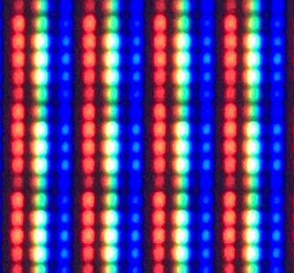
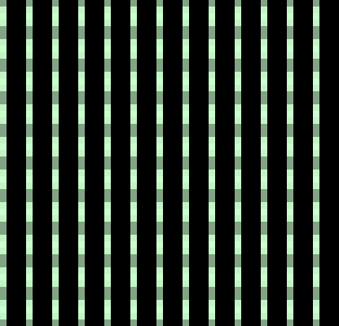
DCIP3B to DCIP3 - ISSUE gets worse, red and blue subpixels light up brighter left and right of the green subpixel.
 //const vec3 dcip3_colour = (scanline_colour * k709_to_XYZ) * kXYZ_to_DCIP3;
 //const vec3 dcip3_colour = (scanline_colour * kDCIP3_to_XYZ) * kXYZ_to_DCIP3;
 //const vec3 dcip3_colour = (scanline_colour * kDCIP3A_to_XYZ) * kXYZ_to_DCIP3;
 const vec3 dcip3_colour = (scanline_colour * kDCIP3B_to_XYZ) * kXYZ_to_DCIP3;
240p WHITE test screen
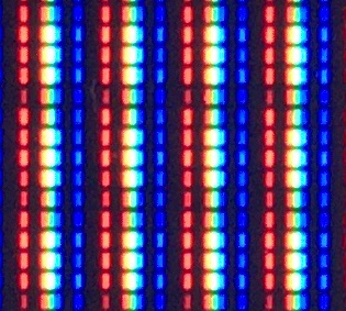
240p GREEN test screen
GPU snapshot of mask, note green has become even less saturated (203,255,206)
Preset used for testing:
hcrt_hdr = "0.000000"
hcrt_colour_space = "2.000000"
hcrt_colour_system = "0.000000"
hcrt_brightness = "0.150000"
hcrt_gamma_in = "2.000000"
hcrt_red_vertical_convergence = "-0.140000"
hcrt_red_scanline_min = "0.550000"
hcrt_red_scanline_max = "0.820000"
hcrt_red_scanline_attack = "0.650000"
hcrt_green_scanline_min = "0.550000"
hcrt_green_scanline_max = "0.900000"
hcrt_green_scanline_attack = "0.130000"
hcrt_blue_scanline_min = "0.720000"
hcrt_blue_scanline_attack = "0.650000"
hcrt_red_beam_attack = "0.720000"
hcrt_green_beam_sharpness = "1.600000"
hcrt_green_beam_attack = "0.800000"
hcrt_blue_beam_sharpness = "1.900000"
hcrt_blue_beam_attack = "0.450000"


