Sony Megatron Colour Video Monitor

Here’s some pics of slot mask on Sega Virtua Racing (a typical look of Virtua arcade game cabinets) on the S95B. When you zoom right in you can see the ‘bobble’ on the horizontal wires but when you zoom out it vanishes which is how it works in person.

Do zoom in on the third close up picture to see both the slot mask and pixels making up the phosphors in detail and in HDR. Apart from the bobble even the slightly larger gap between the blue and red pixels (vertical wires) work well as they seem to match the height of the horizontal wires

7 Likes

The subpixels do look a bit strange in the extreme close up, but perhaps the glow disguises that at greater than nose-to-screen distances. I think what we need are some side-by-side comparisons! Time to see if it passes the Pepsi challenge.

2 Likes

Yeah there’s definitely no getting around the fact it’s going to have slightly odd spacing but you need a camera set to 100 and below ISO to tell I’d say - it’s just too bright to see the individual sub pixels that well but I need to setup my PC in the front room again and find time now that Ive digested the photos a bit and definitely we need to do a pepsi challenge!!!

Just to add one thing I noticed is the larger spacing between the blue and red phosphors in the images but maybe you could argue that’s more like an actual CRT with it’s slightly wider wires between the triads? 🤷

1 Like

Well I was thinking theoretically it should be possible to emulate an electron beam’s width with enough resolution.

Not sure if you were aware but there is this thread on Shmup Forums which details how you can modify the TVL of a CRT to whatever you want by modifying the spot size(electron beam width) There are some very in-depth explanations here(some from Texas Instruments) which might be of use to you https://shmups.system11.org/viewtopic.php?f=6&t=67124&sid=d36961dab98500a962e7bc97015f63c0

Seeing as both CRT and Modern Displays are Raster-type displays, given enough resolution it should therefore be able to recreate the same effect. Although I’m unsure of the math/method involved to do it and how much resolution you would need to do it. I know for a fact though that CRTs were not pixel-perfect by design, at least the ones that used masks. What I’m thinking here is more “line-perfect” rather than pixel perfect.

2160/4=540tvl Pretty sure it’s 3840/4 = 960TVL Or for 4:3 2880/4 = 720TVL Since TVL is the Horizontal Resolution not the Vertical one

For 2: Why would you possibly need that provided by the OS or the Graphics Card? A 3rd party open source software solution would work.

2 Likes

I’ll come back to 1).

As to 2) maybe I’m misunderstanding what you’re after? As far as I can tell youre after a full screen shader that runs over the entire Windows desktop at all times. Have I got that right? If not then why wouldnt ReShade work for you?

So assuming you want the former you might be able to do something like via the likes of a virtual monitor AKA Parsec but obviously you’d need shader support in the virtual monitor driver rather like I was saying for the Nvidia or AMD drivers.

Possibly you might be able to capture the desktop like the snipping tool and display a full screen app over the top but then how do you feed all the mouse keyboard etc events to the Windows subsystem and on top of that good luck with full screen apps. I can’t see how that would realistically work.

1 Like

So to 1) changing the beam spot size isn’t increasing the TVL at all, although I can see it having the effect of doing that. Your TVL is basically fixed to the number of phosphor triads you have and that can’t change. Changing the spot size effectively makes the beam more reactive to the current phosphor and underlying image giving a sharper image.

With shaders you can do this way more accurately as can be seen especially in Reshade where you can have effective TVLs of 2160p if the underlying content is 3840 horizontal resolution.

Basically we change the spot size already and you can change that with the horizontal (and vertical) attack in the Megatron.

TVL is the count of vertical lines across the screen to the height of the screen across i.e a square. That’s why we just use the vertical resolution.

1 Like

Adding to what MajorPain just stated, total TV lines was used by some TV manufacturers like Panasonic and JVC, since more = sounds better. Some CRT spec sheets of monitors on the other hand state a line count for center and another for corners. If you read the thread, the author actually states TVL is a stupid metric after adressing exactly the confusion with total lines by another poster on page 4, but there are also statements of why it can be useful and other things that factor in and what the author was trying to accomplish.

3 Likes

Updated my AutoHDR ReShade addon to work with ReShade 5.4.2 and Sony Megatron for ReShade to latest Retroarch version. You still have to faff about in the fx file to set the right resolution for the intermediate buffers if you want something different to 240p but that’s where ReShade is right now.

Anyway here are the links:

And some pictures of Dead Cells in 240p mode:

7 Likes

Nice. Are these photos of your new OLED? Can we run reshade over scummvm? The libretro core is quite behind the native app version

1 Like

There’s an updated core that builds from latest upstream git, it’s just not on the buildbot (yet). You can get it (and the required helper files) from https://github.com/hunterk/libretro_builds

4 Likes

No they’re of my LCD. That I suppose is something to say I think my LCD is pretty comparable to the QD-OLED to be honest - just it’s on a smaller scale. Not sure about ReShade and Scummvm - my AutoHDR plugin works with both D3D11 and D3D12.

3 Likes

EDIT: all what I’ve just said is nonsense the OLED had gone into some power saving mode! Anyway I’ll keep this here to embarrass myself and entertain you lot. :rofl: I’ll redo this properly now…

Here you go @nesguy 40 year old CRT technology vs cutting edge QD-OLED. Id say it’s about 3-0 to the 40 year technology.

The difference in motion is of course night and day and STILL the OLED is no where near the brightness level of the CRT even if it feels really bright it’s still no where near as bright as the CRT.

Where I’d say the QD-OLED wins out is in size obviously and then if you go off piste with the colours - the QD-OLED can get incredibly saturated colours which is nice to look at in itself if not that accurate - same goes for the LCD.

Now have I got these two as accurate as I did with the LCD, no certainly not but my camera is maybe adding quite a bit of noise because it’s got to be further away than with the LCD because of the size of OLED.

Anyway an interesting test and maybe I can add accuracy a little more if I try out @rafan curves not sure but worth a punt (I’ve been working on something for you @rafan that I hope you’ll like)

4 Likes

This is actually a lot closer in person a lot closer. My camera doesn’t like the moire effects off the OLED at the distance it’s at.

Anyway here are the two images the OLED I’d say is equally as bright as the CRT. They are closer and both these shots are ISO 100.

3 Likes

You can probably use manual focus to get around this. It also happens to me, especially when using Auto Focus until I get the distance and angle right.

With manual it’s a bit easier but I can see the closeness of the fine details despite the colour not looking correct in the photo.

What about motion? Are you able to use BFI?

1 Like

I tried manual as well before and my phone camera still does the same. In motion the CRT destroys the OLED in terms of clarity (I like the Megadrive’s Dynamite Heady first level’s foreground layer and try to read the signage) although I haven’t tried BFI yet as I haven’t found the option but seen as the OLED only just matches the CRT for brightness BFI will obviously unbalance that. I will try it though once I find it - game mode is currently borked appears as they are scaling the image from what looks like 1080p nasty - others must be complaining about this so I’m hoping it gets fixed in a firmware update.

1 Like

Hmmm…did you change the input label on your HDMI input to PC mode? Also did you adjust your Sharpness setting? I was reading up about another recent Samsung set recently where they said that neutral Sharpness is actually at 10 and not 0. Or something like that. It shouldn’t be hard for me to find back the links. Links also talk about how to setup the TV for PC Monitor use.

These are for the Q70A but it’s possible that the same might apply to your set.

2 Likes

Ah just twigged what @Cyber was possibly trying to tell me - have the shot slightly out of focus with manual zoom mode - sorry I was just thinking of it always being in focus. Here’s the best I could take without it becoming a blurry mess and does bring out the colours much closer to what I’m seeing with the naked eye. Thanks Cyber!

2 Likes

Just as another take on this I have the PVMs in the same room as the QD-OLED and although not next to each other I can stand equi distance between them say 12 feet away from each and take photos in roughly the same lighting conditions (it’s day time with the blinds pulled) with the same camera settings 65K 100ISO 1/60 shutter.

Again in person they seem closer to each other. One is 65" and the other 27" so there is that.

I think I need to add back in my Tint option!

Here are the results (QD-OLED top):

2 Likes

Not, exactly. I was just trying to relay my experience. When I use Auto Focus, sometimes the colours keep shifting while I’m trying to get the shot. It could be the focus having to adjusting itself constantly possibly due to the slight movements of my hand or whatever it is.

I notice this colour shifting is a bit easier to control using manual focus. Using manual if the colour is off, I might just have to move very slightly forward or backward, or maybe tilt my device slightly but not enough to make things out of focus though even though this might be desirable at times.

So there’s a particular point and position that looks perfect both focuswise as well as colour wise.

This also applies to a situation where I see some distinct yellow looking “phosphors” between the primary phosphors. I’m not talking about extra subpixels here because if I move slightly forward or backward they also go away and all I see are the primaries.

When I say slightly I mean very minute movements.

I think after “investing” in such lavish TVs another great investment might be a decent phone tripod. Lol. That will take our pics to the next level. A macro lens is another thing.

These pics are awesome though! Glad you’re having even more fun with these things now and I guess you’ve put the question of QDOLED suitability to rest.

You’re welcome!

1 Like

Hi @MajorPainTheCactus

These comparisons are awesome, thanks for taking us along the discovery tour with your new TV!

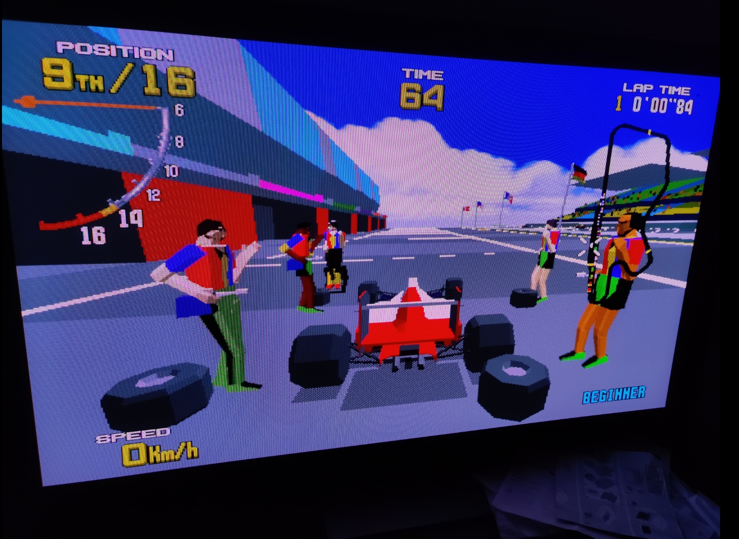
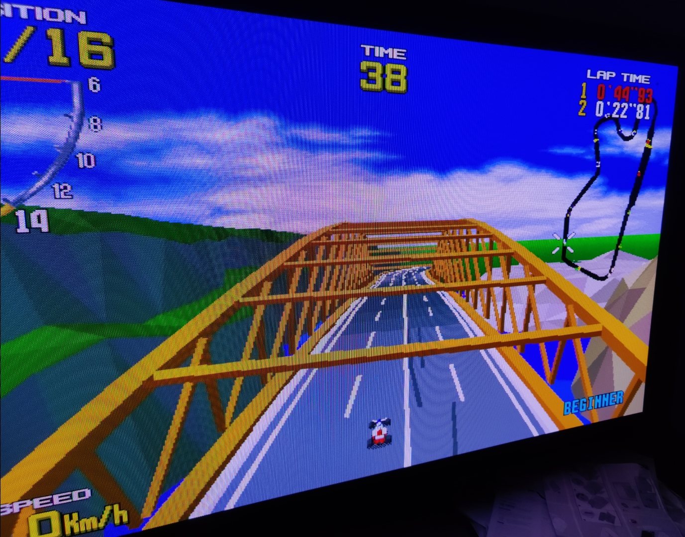
One thing that would be a great addition to your comparison quoted below, is if you could do the exact same two shots, but while having the Megatron run in SDR using these settings:

  • HDR in Retroarch = OFF
  • set shader “SDR: Display’s Colour Space” to DCI-P3

I’m really curious what comes out of that comparison since your TV has 100% coverage of DCI-P3 space (which will be active in native non-HDR mode, at least my monitor is…). It could well be that you’ll get the colours to match better. Two reasons for this could be the DCI-P3 color space coverage is very good with your TV, so the sRGB gamut mapping in the shader may be more accurate for system end result, and/or being in SDR mode, you don’t get the “art” of inverse tonemapping from SDR to HDR possibly interfering. I know you’re a fan of the HDR mode, but this SDR test could prove worhtwhile for colour accuracy.

While we’re at it, I’m really curious as to the colour gamut primary values of your new OLED. For this, if you also have an interest, could you possibly do a quick run of “dxdiag.exe” on the windows command prompt and then on the screen that opens click “save all information”, open this text file and search for each of the two following lines separately and share the line -below- each that starts with “Color Primaries:” .

 Display Color Space: DXGI_COLOR_SPACE_RGB_FULL_G2084_NONE_P2020
 Display Color Space: DXGI_COLOR_SPACE_RGB_FULL_G22_NONE_P709

Regardless, good job on the comparison of side by side!

4 Likes