
This is the chip the SNES used, probably rebranded. Takes RGB and converts it to S-VIDEO/COMPOSITE
2 Likes
Great work! I hope this topic continues to serve as a catch-all for such finds.
1 Like
If we could translate Japanese it could be useful heh
1 Like
Rough translated on AI and here it’s what is doing and result

// Input: either a texture with RGB or you can feed color another way
#define uPixelClock 13.5e6    // pixel clock in Hz (e.g. 13.5e6 typical for SD sampling)
#define uSubcarrierHz 3.57e6  // chroma subcarrier freq (NTSC = 3579545.0, PAL = 4433618.0)
#define uModePAL 0.0         // 0 = NTSC, 1 = PAL (pal alternation enabled)
#define uChromaGain 1.0    // scale factor for chroma carrier amplitude
#define uDeltaRdeg 1.0     // ΔR in degrees (datasheet typical ~ +1°)
#define uDeltaBdeg 4.0     // ΔB in degrees (datasheet typical ~ +4°)
#define uBurstPhaseDeg 180.0 // burst phase relative to R-Y (deg). Datasheet implies ~180°
#define uPixelsPerLine SourceSize.x // visible pixels per line (e.g. 720)

// coefficients: Rec.601-like luminance for simple RGB->Y
const vec3 Ycoeff = vec3(0.299, 0.587, 0.114);

// Helper
float deg2rad(float d) { return d * 3.14159265358979323846 / 180.0; }

void main() {
    // Read the RGB input
    vec3 rgb = texture(Source, vTexCoord).rgb;

    // Compute luminance and color-difference signals
    float Y  = dot(rgb, Ycoeff);      // 0..1
    float RY = rgb.r - Y;             // R - Y
    float BY = rgb.b - Y;             // B - Y

    // Convert ΔR/ΔB and burst phase to radians
    float deltaR = deg2rad(uDeltaRdeg);
    float deltaB = deg2rad(uDeltaBdeg);
    float burstPhase = deg2rad(uBurstPhaseDeg);

    // Calculate pixel time index t_pixel
    // We compute an approximate continuous time value per pixel:
    // t_pixel = (lineIndex * pixelsPerLine + pixelIndex) / pixelClock
    // For simplicity we use pixel coordinates to derive these values.

    float pixelIndex = floor(vTexCoord.y*SourceSize.y)*SourceSize.x + vTexCoord.x*SourceSize.x;
    //float t_pixel = pixelIndex / uPixelClock;

    // Subcarrier phase
    float phase = 2.0 * 3.14159265358979323846 * pixelIndex * uSubcarrierHz / uPixelClock;

    // PAL alternation: flip one carrier axis 180° every line
    if (uModePAL == 1) {
        // flip sign every other line (equivalent to add PI)
        if (mod(floor(vTexCoord.y*SourceSize.y), 2.0) > 0.5) {
            phase += 3.14159265358979323846; // add pi on odd lines
        }
    }

    // Apply small datasheet phase errors (ΔR, ΔB). The datasheet defines ΔR = eR - 90°,
    // but here we allow direct tuning offsets (additive).
    float phaseR = phase + deltaR;  // used with sin()
    float phaseB = phase + deltaB;  // used with cos()

    // Build modulated chroma (carrier)
    // We use sin for R-Y and cos for B-Y to represent quadrature (90° separation)
    float chroma = (RY * sin(phaseR) + BY * cos(phaseB)) * uChromaGain;

    // Compose outputs:
    // YO: luminance + sync (we don't generate sync here; if needed add negative pulses)
    // CO: chroma (modulated) - real hardware filters & levels would differ; normalize
    // VO: composite = Y + chroma (clip to 0..1)
    float composite = clamp(Y + chroma, 0.0, 1.0);

    // Optionally: overlay the burst reference (for debugging), gate it during burst region
    // (Not implemented: you'd need horizontal timing + burst window timings.)

    // Output as grayscale visualization of composite on all channels
    FragColor = vec4(vec3(composite), 1.0);
}
Had to correct some dumb errors of AI like using gl_FragCoord for pixel index but otherwise pretty amazing job in translating to a shader,
1 Like
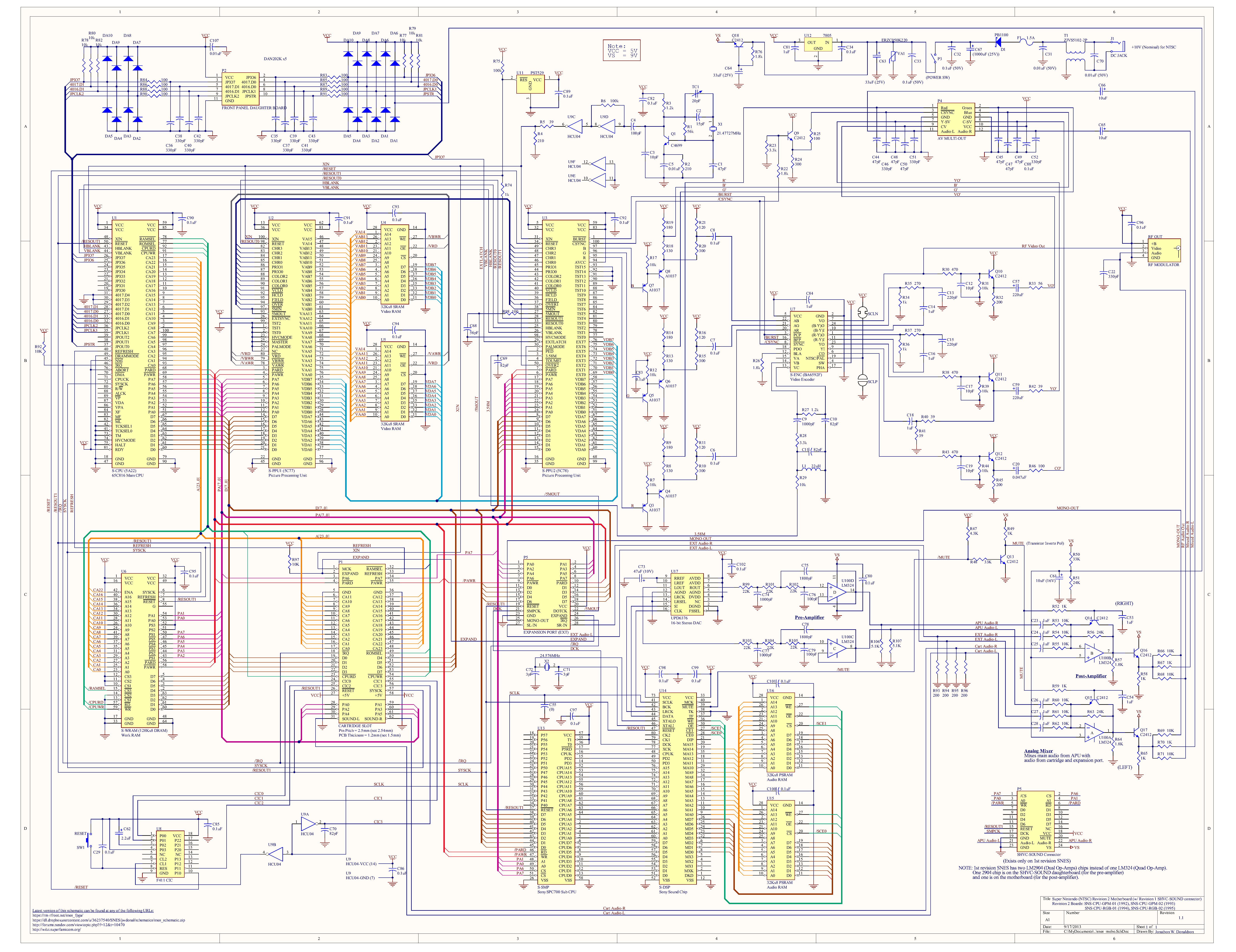
Yes, the ones that I’ve seen. This is particularly easy to see on the SNES schematic:

Those two identical blocks on the right (for example, R34, R35, C13, and C14) are the two filters for the chroma components (R-Y and B-Y). They use all the same parts and so filter both components the same way.
Some consoles modulate the chroma and then use a band-pass filter rather than low-passing each of the components separately. Some later chips have the filter on-chip rather than relying on the designer to build one off-chip. But I haven’t seen any that filter the chroma components to different bandwidths.
3 Likes
the irony is in PAL they made new PAL-D that is more expensive to make the colors better, while in NTSC they did the opposite, even though the bandwidth for NTSC chroma is originally less than PAL, so that why I remember that NTSC was bad and came after SECAM in the lack of color accuracy (Especially in terms of color oversaturation and its proximity to RGB), and btw we used to associate PAL with light colors (which was often crushed in SECAM, the image in secam was generally oversaturated), it’s worth pointing that we did not have much contact with NTSC and most of the NTSC exposure was in the game consoles
Inside the chip

Those “I F” (intermediate frequency filters) limit the actual bandwidth inside the chip seperately. In PAL it uses the same line for both, so they are different in NTSC, same in PAL. Those resistors R34 etc are low pass filters. Or i could be wrong lol

2 Likes
I can’t tell what the"I F" blocks are from the datasheet, but I don’t see any in the chroma path. The chroma output is on pins 24 and 1, and the input is on pins 11 and 10. It loops back into the chip to allow the designer to use their own filter.
ok so SCLN and SCLP should be some jumpers that activates N(TSC) or P(AL) or something on pin 19. Need some investigation, looks like colors come as raw RGB into pins 20,21,22 from PPU2 pins 97,96,95.
If you look the diagram looks like raw RGB passes the YIQ matrix and comes back to pins 9,10,11 as Y,I,Q to be further processed, add phase etc 
It ends on pin 7 of the S-ENC as Video Out, it is send to RF plug and multi-out video plug then. Internal filters of the chip should be the ones that limit bandwidth after it passes pins 9,10,11 or after pins 8,19 (probably not)
2 Likes
This is what I’ve always done. I allow my eyes and brain, including my “unreliable” memory to be the judge, while also balancing this against trying to not clip colours and highlights and maintain gradients, contrast and details.
Great find and it makes complete sense. This is sometimes done in video and audio capture/recording and production as well to avoid clipping and preserve dynamic range.
1 Like
Quick example. First is a run of the mill guest-advanced RGB preset, second is guest-ntsc with tvoutweaks doing the stuff just described, leaving all the mask/scanline/brightness/etc stuff the same. Mask adjusted to 50% for tolerable viewing on non-HDR displays:
I think this is approximating the differences seen in the example @DariusG posted
There are certain standards in formats like NTSC YIQ channel bandwidth, or NTSC-J, clearly documented in various sources that one cannot just revision, ammend them or what, without having solid and valid points about it. Actually cannot cancel it at all lol. It is what it is.
Is this about the equal bandwidth thing?
I guess this part is somewhat iffy.
Did anyone read the document i posted with NTSC bandwidth standard, that if you make them equal you’ll introduce hell of a lot of crosstalk between I and Q? And PAL U/V needs extra work on decoder side to get rid of the crosstalk because they are equal?
1 Like
I see it now, yeah. I’ll leave this to you and beans 
I think if they were actually using the asymmetric IQ bandwidth, they must have been applying a pretty aggressive automatic gain control / color boost.
It would still be nice to have a definite answer, though!
Remember: only do the YIQ conversion once! You don’t want to repeat this in your shader chain. I made this mistake in the Mega Man example I just posted.
Here are the shaders that do the YIQ thing:
TVouttweaks
GTUv50
NTSC Colors
nes-color-decoder
any recent composite video shader
Probably missing a few. I think these can all be combined with ntsc-adaptive without “doubling up” on effects.
EDIT: yeah nvm, this is all kind of mysterious to me, still. I think the general principle is correct, though- only do the YIQ conversion once. How this plays out exactly with all the shaders gets a bit messy 
If you deep dive the schematics it’s possible to create a most faithful representation, e.g. those R35, R37 270 low pass I,Q to less than 2.7mhz and go back to chip, then approximate the detail loss there (assuming full detail is like 5mhz or something), then the next one, enter the S-ENC do what it does and so on. It will take so much time that you’ll do only one system like blargg did lol.
Start from ppu2 follow the color line and emulate what’s going on. I’ve also seen some ntsc encoders that divide Q like Q/2 in their data sheets after matrix pass. There is a truckload of small details on this rabbit hole, phase shiftings 1 degree on sin, 4 on cos and more and more and more lol
2 Likes
I think the document is saying something else. Filtering both at 0.6 MHz should result in the least crosstalk.
The crosstalk they mention is due to the asymmetrical sidebands of I when it is limited to 1.3 MHz. If you allow more than 0.6 MHz of bandwidth for either (or both) of I and Q and center them on the chroma subcarrier, you’ll have chroma data reaching beyond 4.2 MHz. That is not allowed for broadcast (but it may work with composite input). To keep everything under 4.2 MHz, you need to filter out the higher frequencies and you are left with a vestigial sideband. The phase differences that result from this can introduce crosstalk when you demodulate.
From the same book, p. 435:
When using lowpass filters with a passband greater than about 0.6 MHz for NTSC (4.2 – 3.58) or 1.07 MHz for PAL (5.5 – 4.43), the loss of the upper sidebands of chrominance also introduces ringing and color difference crosstalk.
This isn’t really an issue for composite, though. Unlike broadcast, composite is not limited to 4.2 MHz and so we don’t have to cut the upper sideband.
If you deep dive the schematics it’s possible to create a most faithful representation, e.g. those R35, R37 270 low pass I,Q to less than 2.7mhz and go back to chip, then approximate the detail loss there (assuming full detail is like 5mhz or something), then the next one, enter the S-ENC do what it does and so on. It will take so much time that you’ll do only one system like blargg did lol.
I was curious and I actually did try to simulate these low pass filters, but I think either I am doing something wrong or the capacitor values in the schematic are incorrect. According to my simulation, they’d make terrible filters. Like, -6 dB at 4-5 MHz or something (I don’t remember off the top of my head). 🤷
1 Like
That’s a huge rabbit hole right there, lot’s of smaller rabbit holes in each step, notice how emulator devs never touch it to offer some Composite/RGB option, they just bypass that part and end up directly to RGB video out lol. They will just forget S-ENC was inside there.
1 Like