Ten years of CRT shaders

This weekend is the tenth anniversary of my first public post about a CRT shader I was working on, which to my knowledge was the first CRT shader.

I should stress that there were important predecessors, such as the long history of scanline filters as well as Blargg’s ground-breaking NTSC libraries. And there were CPU-based television or CRT simulations such as XAnalogTV from 2003 and the CRT simulation in Stella that was announced a few weeks before my first shader. I should also highlight the very impressive crtsim from a few months later.

I’m impressed by a lot of the ongoing discussion and development, although unfortunately I am not completely up-to-date on the full spectrum of CRT shaders today. I’d like to go through the simulation pipeline and try to highlight some successes and areas that could use more attention.

  1. NTSC/PAL video decoding. Blargg's filter is still great and there are also some shaders. But it would be better to more accurately simulate some decoders used in actual televisions, which also made use of comb filters. (I played with the latter a few years ago.) Here there's also a need for better integration with the emulator, so that an accurately encoded signal can be passed through to the decoding shader.
  2. Video amplifier. This is somewhat connected with the previous step, since the problem can be treated as an issue of signal processing. Since this applies before the gamma ramp, it can cause darkening of high-contrast areas — this is why gamma charts traditionally use horizontal lines. I'm not aware of any serious attempt to accurately simulate this. One way of doing so would be to display some test images on a CRT. These would have to contain high-contrast areas with varying horizontal frequency; a filter could then be designed to reproduce this in the simulated CRT. There's a good discussion of this in the following article:
    Hu, Q.J. & Klein, S.A. (1994). Correcting the adjacent pixel nonlinearity on video monitors. Human Vision, Visual Processing and Digital Display V BE Rogowitz & JP Allebach, Eds, Proc. SPIE 2179, 37-46.
  3. Gamma ramp/tone curve. This is under reasonable control, although it would be nice to have some real measurements on historical displays. Also: people who write shaders should be very careful about unintended sources of nonlinearity such as scanline blooming or glow effects. It could be useful to display a gamma chart to test the full effect of the shader.
  4. Geometry. In principle this can include curvature of the screen along with the usual set of adjustments: pincushion, trapezoid, rotation, etc. Misconvergence was a common and important defect that is simulated in e.g. MAME's HLSL and CRT-Royale. I think it's also important to make the raster behave more dynamically, and it's encouraging to see the "raster bloom" effect implemented in crt-guest-dr-venom.
  5. Spot shape. Here a Gaussian or some variant is reasonable. It would be nice to have some real empirical input to make any blooming effect that varies the spot shape be realistic.
  6. Halation or veiling glare. I will start by quoting myself from 2011 (with a couple minor edits):
    Recently I've looked into the issue of veiling glare or halation (which seem to be the same thing, as far as I can tell). Here are a few references:
    • The first one (alternative link) basically establishes that halation is important for subjective image quality.
    • The second one (alternative link) is the best of the three. First, it describes the sources of veiling glare:
      • Internal reflection in the faceplate. This is the most important, and is a local effect.
      • Light leaking out the back of the phosphor layer, scattering inside the CRT, and making its way back out the front. This tends to have a uniform effect over the whole display.
      • Electrons scattering between the phosphor layer and the shadow mask. This is a short-range effect.
      • Electrons backscattering off the shadow mask, and eventually hitting the phosphor layer. This is a long-range effect, like light leakage.
      Then they went on to compare a simulation with measurements performed on a monochrome CRT. One test that might be possible to repeat is to display a single bright spot in the center of the screen, block it with some black paper, then take a photo of the veiling glare (although I should point out that they disabled the beam deflection, which would result in a much brighter spot). Figure 3 gives a nice picture of the effect.
    • The third article (alternative link) shares some authors with the second, and has some somewhat more sophisticated measurements of veiling glare.
    Some version of these effects is implemented in various shaders including my own. Note that the effects involving light yield coloured halation, whereas effects involving electrons will eventually hit a random phosphor and yield monochromatic halation. Again, some careful comparison with real CRTs would be useful.
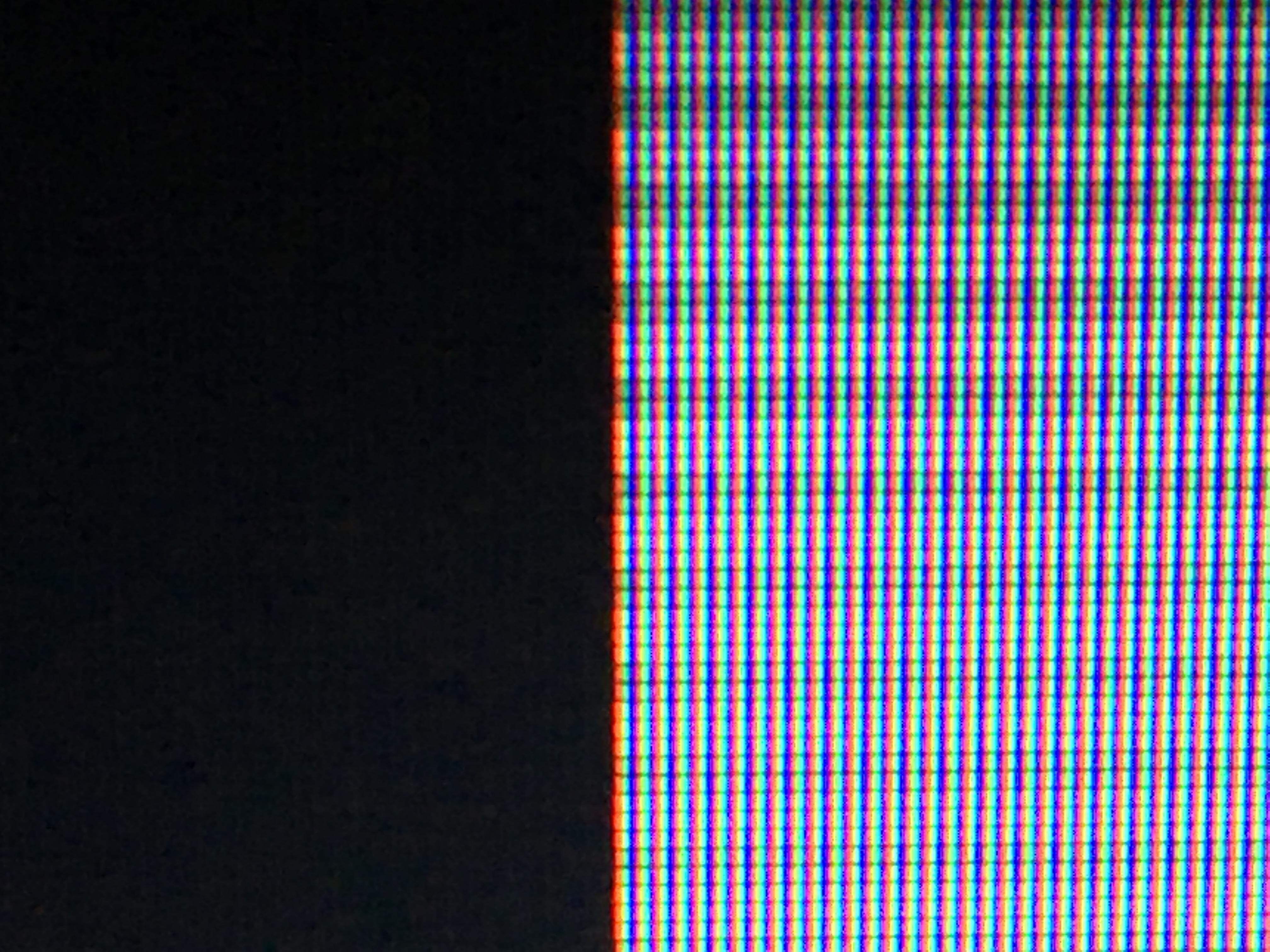
  7. Shadow mask / aperture grille phosphor pattern. With 4K displays, it should be possible to produce a reasonably realistic result. One problem I should point out with many currently used patterns: they fail to account for the RGB subpixel pattern of the LCD they will be shown on. For instance, a common and simple aperture grille pattern has single-pixel RGB stripes. But at native resolution on an LCD, this appears as R...G...BR...G...BR...G...B, i.e. the green stripes have three dark subpixels on each side but there is no dark subpixel between B and R. Two simple solutions: either add a black stripe between B and R, or double the number of bright subpixels with the pattern R..RG..GB..B, which is also four pixels wide (red, yellow, cyan, blue).
  8. Colour primaries and white point. With a colour meter these should be measurable and we can try to replicate them, or we can rely on manufacturers' specs. I think it's important for anyone who produces a colour correction to specify whether it came from an actual reference or based on what "looks right"; the latter is really not trustworthy.
  9. Short time behaviour of phosphors. This is tough to simulate on sample-and-hold LCDs. Black frame insertion / backlight strobing should help; ideally the "on" time for the backlight should be as short as possible.
  10. Phosphor decay/persistence. It can be tempting to dismiss this as negligible because the exponential decay times are much shorter than a frame. However, for sRGB the intensity has to decay below (1/255)/12.92=0.0003 to be negligible, which corresponds to a lot of decaying. Furthermore, the decay can eventually follow a power law, which is much slower than exponential. The result is that a visible excitation might remain even after a second has passed. There are some good references here including some decay curves, which are colour-dependent. I included a power law decay in crt-geom-deluxe — it's trickier to implement than exponential.
  11. Miscellaneous. Having the image reflect off the frame of the CRT could add to the immersion. Interlacing should be better supported starting from the emulator.
It would be interesting to hear others' perspectives. Are there important issues that I've missed? Is there some additional progress that I've overlooked?
16 Likes

Fantastic write-up!

Chief Blur Buster / Inventor of TestUFO here.

We’re the website that extolls the benefits of retina refresh rate displays – you can simulate phosphor decay more accurately by using multiple refresh cycles per emulated Hz. Such as 4 refresh cycles for 60fps @ 240Hz and 8 refresh cycles for 60fps at 480Hz.

Now, imagine simulating phosphor decay at 1ms granularity on a future 960Hz display. And throwing on rolling-window scan software BFI too! (Mimicking CRT scanning at the millisecond granularity!)

More accurately temporally emulating CRT scanning & CRT phosphor decay – we anticipate that temporal emulation will become accurate enough to emulate CRT rolling scan (at the coarse rolling fuzzybar level) and CRT phosphor decay eventually. 960 Hz displays provide 16 refresh cycle opportunities for emulated 60Hz. (960 / 60 = 16). This can visually accurately temporally emulate an impulse-driven CRT refresh cycle. Metaphorically – it is akin to playing back a full-dynamic range high speed 960fps video of a CRT (not overexposed) back onto a 960Hz display in realtime – it then thus looks indistinguishable to a real CRT via human eye.

To achieve sufficient accuracy to human vision acuity levels – you don’t necessarily have to emulate a single phosphor dot – just emulate a millisecond worth of CRT scanning (photons-wise) – which will look like a horizontal strip of frame, with a fuzzy edge gradient towards black (like you see in a freezeframe of a high speed video of CRT)

Even now we have 240Hz on the market – high enough to attempt rolling-window software BFI (simulated CRT scanning at roughly quarter-screen-height).

The world has achieved spatial accuracy via retina displays with MAME HLSL. The higher the refresh rate, the more fine-granularity you can temporally accurately emulate a historic display – closer to human vision acuity margins – the impulsed look, the scanning look, the phosphor decay look, the zero-blur look, even the parallelogram-shape of a CRT that occurs during eyerolls! Currently, 1000Hz begins to start to pass the uncanny valley sufficiently for this quality of temporal emulation of a CRT.

1000Hz is already in the lab. We anticipate commercialized ~1000Hz by roughly year 2030.

More reading: Retina refresh rate benefits for emulators of the 2030s.

Oh, and if you haven’t seen it yet – Blur Busters Law: The Amazing Journey To Future 1000Hz Displays (includes scientific references and animations – best viewed on a desktop computer)

3 Likes

good to hear from you, and good roundup!

The amount of halation caused by internal reflection on the glass seems to vary quite a bit. I have an NEC XM29+ that has an outrageous amount of that, while my Sony PVMs have a lot less. They’re also a lot smaller than the NEC, though, so I’m not sure how much of it has to do with glass thickness on larger monitors.

I’ve seen where people have used reshade to do frame reflection. It should be possible in RetroArch, as well, possibly using mirrored-repeat and in-shader integer scaling.

Do you have a link to the crt-geom-deluxe code handy? I don’t think I’ve seen any more than the json reference files in MAME’s source tree. EDIT: ah, here it is (just had to search for one of the function names; I used ‘bkwtrans’ :slight_smile: ):

EDIT: wth? I remember that thread on byuu’s forum with your decoding shader but don’t remember the actual shader files. :open_mouth: I’ll get those pushed up to the quark repo and get them converted to RetroArch’s formats, as well.

5 Likes

@hunterk

Seems to be first, this isn’t actual shader code but has important settings and references other things.

Then this seems like a good place to start,

The Effects and Chains folders seem to have more reference and important information in them.

The shaders folder has a GLSL folder in with more folders and bin files, which in my text editor on my phone’s file browser (mixplorer) seem to be really badly formatted glsl-ish code. Hope this helps sorry if I’m wrong.

I agree, it would be exciting to work with a display that can show many frames per emulated frame. For now, I’m still stuck with 60Hz, though.

Regarding crt-geom-deluxe: I’ve just submitted a pull request with a minor update, so it’s probably best to adapt the version in my tree. And yes, the actual uncompiled shader code is in

src/osd/render/bgfx/shaders/crt-geom

The metadata is stored in two places:

bgfx/effects/crt-geom

and (more importantly)

bgfx/chains/{crt-geom,crt-geom-deluxe}.json

Finally, the overlay patterns are in

artwork/bgfx/chains/crt-geom
3 Likes

I got crt-geom-deluxe going in slang and that phosphor decay effect is very nice. Great job on that.

3 Likes

Are we possibly getting this in the repo (haven’t checked yet), also wondering if a GLSL port would be possible? Always been a fan of crt-geom.

EDIT: crt-geom-deluxe is in the slang repo for anyone that is interested.

Can’t do it in GLSL, as it requires the “feedback” functionality for the phosphor persistence effect.

1 Like

Ohhh, well thanks for letting me know, lol.

One final question for the night, is the faux-bezel reflection thing you did with guest.r’s shader, is that able to be done in GLSL?

Yeah, that one’s possible. Bit of a hassle with all of the NPOT texcoord stuff, though.

1 Like

This seems like it should be really easy to implement. Any way someone with skillz could add this option to the dotmask shader, glsl? (red, green, blue, black) @hunterk

The only downside is that it drops the “TVL” from 360 to 270 if on a 1080p screen, but that’s still pretty close to an inexpensive CRT TV. Should look nice.

How would one go about matching spot size to color intensity in an empirical way? I’m guessing this is something that varied a lot depending on the qualities of the CRT being used (TVL, beam focus, etc).

Thank you for posting crt-geom-deluxe, it’s quite a significant upgrade to the old one and the halation looks smoother than with many other shaderers.

crt-geom-deluxe, crt-geom and crt-cgwg-fast all exhibit some slight (1 pixel wide) horizontal ringing when having them run in linear space*. It’s almost invisible with halation and curvature active, but noticable without. Is this caused by the Lanczos kernel? What would be a good way to fix it? (Since choosing a lower kernel size of a=1 intead of a=2 removes the secondary lobes but leaves other artifacts…)

*crt-cgwg-fast ususally doesn’t have linear as an option, I added for testing

2 Likes

Whoa! Shaders look really cool!

Here are a couple old papers where this was studied: 1, 2 (alternative links: 1, 2). In both cases they used a scientific CCD camera and a monochrome CRT; the latter simplifies things by not having a shadow mask.

Without having specialized hardware, the vertical profile could probably be studied using an aperture grille CRT and a modern digital camera in raw mode and with a decent macro lens. The exposure time should be at least one frame and ISO should be set to avoid clipping. Then after extracting beam profiles for various intensities, the normalized profiles could be compared.

And yes, this probably varied a lot.

1 Like

The horizontal filter should actually be doing two things: first, account for the limited bandwidth of the video amplifier (#2 in the top post), which applies to the encoded (nonlinear) signal, and second account for a horizontal width in the beam, which should be done in linear space. As it is, the shader only has the one Lanczos filter, which would be most appropriate for the first step (in nonlinear space).

There can be real ringing in the first step — this could be somewhat adjusted using the sharpness control on an analog TV. If you dislike the ringing from Lanczos, you could simply replace it with something else: for instance, linear interpolation doesn’t have any negative lobes. If the shader had both horizontal filters, then a Gaussian horizontal beam profile could help to obscure ringing from the first step of filtering.

2 Likes

These are some really great papers; too bad most of it is over my head :smiley:

How much of these findings have been incorporated into current shaders? Such as:

-the pixel brightness being determined by the previous two pixels in the raster

-the pixel brightness being determined by the proportion of the screen that is illuminated

-other scientific research that has been incorporated into current shaders?

How would one go about extracting the beam profiles from photos, normalizing them, and then comparing them? Does this result in a formula for matching spot size to color intensity?

This is related to my point #2 in the top post. The point is to remember that a CRT is an analog device, and in particular the signal varies continuously along the scanline. Once you add the nonlinearity of the gamma ramp, this behaviour is bound to occur. Actually, this is discussed nicely in the reference I gave in that post.

Shaders that apply the horizontal filter before the gamma ramp have this effect to some degree, although I can’t say how accurate it is. As far as I know, all shaders use a symmetric filter, whereas an asymmetric one might be more appropriate.

I don’t think any shader simulates this. The closest I’m aware of is the “raster bloom” effect, which may have the same cause.

The top post represents my best understanding of the current situation.

First, one would have to a display one-pixel-tall horizontal line on the display, with adjustable intensity; it’s probably best to do this separately for each primary colour. Ideally the resolution of the photo should be high enough that a phosphor strip is several pixels wide. I would try to work from the raw-format photo. Identify a vertical strip of pixels that lies in the middle of the phosphor strip, and extract the measured brightness in the subpixels of the correct colour, along this strip.

Plotting this brightness versus the distance along the vertical strip should give a picture of the beam profile. To compare different intensities, it is probably necessary to subtract an ambient brightness measured far from the center of the beam, and then divide by the maximum value measured at the center.

Finally, some modeling will be required to determine how the shape varies with intensity. The standard picture is a Gaussian, but the appropriate model will depend on how the results look.

3 Likes

Excellent info in these posts; thanks for taking the time to reply. Hopefully someone with more expertise than I have will find this useful as a starting point.

Get to it, shader authors! :smiley:

I think it’s also worth pointing out that the Lottes shadowmask and dotmask effect also don’t account for the LCD sub pixels. The only pattern I know of that takes into account the LCD sub pixels, other than those you mentioned, is magenta, green, magenta, green, etc. (edit: this is perhaps stating the obvious since this is the mask used in CRT-geom). This gives you RxBxGxRxBxGx etc, assuming a standard RGB subpixel structure), which reverses the order of the “phosphors” but results in even spacing between them. For some reason, this still appears as RGB in a close up photo: