It’s crazy complex you see 20 lines in main program then it calls a function that calls another function and another and another 
Way more complex than anything in ntsc shaders folder. Probably 10 or 20 times more code than the most advanced ntsc.

It’s crazy complex you see 20 lines in main program then it calls a function that calls another function and another and another
Way more complex than anything in ntsc shaders folder. Probably 10 or 20 times more code than the most advanced ntsc.
Hmmm…Maybe that why it works and looks so good!
Talking about some serious rabbit hole there

Yeah, that’s been my experience (and suspicion), as well.
This one (https://github.com/LMP88959/NTSC-CRT) looks like it might be a better target, either as a port to shader or implemented as a RetroArch-format video filter. Since it’s pretty self-contained, it may even integrate with cores directly /shrug.
Have you tried forcing the resolution it expects?
var fbopts = [
 { color: regl.texture({ width: 720*2, height: 262 }) },
 { color: regl.texture({ width: 720*2, height: 263 }) }
]
I am trying various tricks to make it look like it should look. Let’s see.
check the code
PASS 1
#version 130
/* PASS 1

return the modulated floating point `signal` from `0.0` to `+1.0` for `uv` in unit coordinates
(values from 0 to 1, inclusive) where `(0,0)` is the bottom-left. the `picture` texture should have
its `(0,0)` at the bottom-left too.

`n_lines` is the total number of lines (262 or 263).
*/


// Parameter lines go here:


#define pi 3.141592

#if defined(VERTEX)

#if __VERSION__ >= 130
#define COMPAT_VARYING out
#define COMPAT_ATTRIBUTE in
#define COMPAT_TEXTURE texture
#else
#define COMPAT_VARYING varying
#define COMPAT_ATTRIBUTE attribute
#define COMPAT_TEXTURE texture2D
#endif

#ifdef GL_ES
#define COMPAT_PRECISION mediump
#else
#define COMPAT_PRECISION
#endif

COMPAT_ATTRIBUTE vec4 VertexCoord;
COMPAT_ATTRIBUTE vec4 COLOR;
COMPAT_ATTRIBUTE vec4 TexCoord;
COMPAT_VARYING vec4 COL0;
COMPAT_VARYING vec4 TEX0;


vec4 _oPosition1;
uniform mat4 MVPMatrix;
uniform COMPAT_PRECISION int FrameDirection;
uniform COMPAT_PRECISION int FrameCount;
uniform COMPAT_PRECISION vec2 OutputSize;
uniform COMPAT_PRECISION vec2 TextureSize;
uniform COMPAT_PRECISION vec2 InputSize;

// compatibility #defines
#define vTexCoord TEX0.xy

void main()
{
    gl_Position = MVPMatrix * VertexCoord;
    TEX0.xy = TexCoord.xy;

}

#elif defined(FRAGMENT)

#ifdef GL_ES
#ifdef GL_FRAGMENT_PRECISION_HIGH
precision highp float;
#else
precision mediump float;
#endif
#define COMPAT_PRECISION mediump
#else
#define COMPAT_PRECISION
#endif

#if __VERSION__ >= 130
#define COMPAT_VARYING in
#define COMPAT_TEXTURE texture
out COMPAT_PRECISION vec4 FragColor;
#else
#define COMPAT_VARYING varying
#define FragColor gl_FragColor
#define COMPAT_TEXTURE texture2D
#endif

uniform COMPAT_PRECISION int FrameDirection;
uniform COMPAT_PRECISION int FrameCount;
uniform COMPAT_PRECISION vec2 OutputSize;
uniform COMPAT_PRECISION vec2 TextureSize;
uniform COMPAT_PRECISION vec2 InputSize;
uniform sampler2D Texture;
COMPAT_VARYING vec4 TEX0;

// compatibility #defines
#define Source Texture
#define vTexCoord TEX0.xy

#ifdef PARAMETER_UNIFORM
// All parameter floats need to have COMPAT_PRECISION in front of them
uniform COMPAT_PRECISION float SHARPX;


#else
#define SHARPX 0.5


#endif

#define time float(FrameCount)

vec3 rgb_to_yiq(vec3 rgb) {
  float y = 0.30*rgb.x + 0.59*rgb.y + 0.11*rgb.z;
  return vec3(
    y, -0.27*(rgb.z-y) + 0.74*(rgb.x-y),
        0.41*(rgb.z-y) + 0.48*(rgb.x-y)
  );
}

vec3 yiq_to_rgb(vec3 yiq){
return vec3(yiq.x + 0.9469*yiq.y + 0.6236*yiq.z,
            yiq.x - 0.2748*yiq.y - 0.6357*yiq.z,
            yiq.x - 1.1*yiq.y + 1.7*yiq.z);
}


//const float FSC = 5e6*63.0/88.0;
const float FSC = 3579545.5; // 5e6*63.0/88.0
const float PI = 3.1415927410125732;
const float L_TIME = 6.35555e-5;
const float P_TIME = 5.26e-5;
const float FP_TIME = 1.5e-6;
const float SP_TIME = 4.7e-6;
const float BW_TIME = 0.6e-6;
const float CB_TIME = 2.5e-6;
const float BP_TIME = 1.6e-6;
const float Q_TIME = 2.71e-5;
const float EQ_TIME = 2.3e-6;

float modulate_t(float t, vec3 rgb) {
  vec3 yiq = rgb_to_yiq(rgb);
  float s = sin(2.0*PI*t*FSC);
  float c = cos(2.0*PI*t*FSC);
  return yiq.x*(100.0-7.5) + (c*yiq.y + s*yiq.z)*20.0 + 7.5;
}

float modulate_uv(vec2 uv, float n_lines, vec3 rgb) {
  float v_lines = n_lines - 20.0;
  float t = uv.x*P_TIME + floor(uv.y*(v_lines-1.0)+0.5)*P_TIME;
  return modulate_t(t, rgb);
}

float modulate(vec2 v, float n_lines, vec3 rgb) {
  float v_lines = n_lines - 40.0;
  float line = floor((1.0-v.y)*n_lines+0.5);
  vec2 uv = v
    * vec2(L_TIME/P_TIME, n_lines/v_lines)
    - vec2((L_TIME-P_TIME)/P_TIME, 0.0);
  float hblank = step(v.x, (L_TIME-P_TIME)/L_TIME);
  float vblank = step(1.0-(n_lines-v_lines)/n_lines, v.y);

  float odd = mod(n_lines,2.0);
  float vsync_pre = step(0.0,line)*step(line, 3.0);
  float vsync_pulse = step(3.0,line)*step(line,6.0);
  float vsync_post = step(6.0,line)*step(line,9.0);

  float vt = 0.0;
  vt += FP_TIME/L_TIME;
  float syncpulse = step(vt,v.x) * step(v.x,vt+SP_TIME/L_TIME);
  vt += SP_TIME/L_TIME;
  vt += BW_TIME/L_TIME;
  float colorburst = step(vt,v.x) * step(v.x,vt+CB_TIME/L_TIME);
  vt += CB_TIME/L_TIME;
  float signal = modulate_uv(v, n_lines, rgb);
  //signal *= 1.0 - hblank;
  //signal -= 40.0 * syncpulse;
  //signal += sin(2.0*PI*FSC)*20.0*colorburst;
  signal *= 1.0 - vblank;
  signal -= 40.0 * vsync_pre * step(mod(v.x,0.5)*L_TIME,EQ_TIME);
  signal -= 40.0 * vsync_pulse * step(mod(v.x,0.5)*L_TIME,Q_TIME);
  signal -= 40.0* vsync_post * step(mod(v.x,0.5)*L_TIME,EQ_TIME);
  return (signal + 40.0) / (120.0+40.0);
}

void main(){

vec2 vpos = (vTexCoord);

vec3 res = COMPAT_TEXTURE(Source,vTexCoord).rgb;
float n_lines = 262.0+1.0*mod(time,2.0);
float signal = modulate(vpos, n_lines, res);

FragColor = vec4(signal, 0.0, 0.0, 1.0);
}

#endif
PASS 2
   #version 130

/* PASS 2

decode a texture `signal` with its red channel set as modulated ntsc from `0.0` to `+1.0` for
`uv` in unit coordinates (values from 0 to 1, inclusive) where `(0,0)` is the bottom-left.

`n_lines` is the number of lines (262 or 263).

`width` and `height` are the decoded size of the resulting visual image (use `720,485`).

For higher precision you can use a floating point texture for `signal` although in practice it
doesn't appear to make much of a difference.
*/

// Parameter lines go here:


#define pi 3.141592

#if defined(VERTEX)

#if __VERSION__ >= 130
#define COMPAT_VARYING out
#define COMPAT_ATTRIBUTE in
#define COMPAT_TEXTURE texture
#else
#define COMPAT_VARYING varying
#define COMPAT_ATTRIBUTE attribute
#define COMPAT_TEXTURE texture2D
#endif

#ifdef GL_ES
#define COMPAT_PRECISION mediump
#else
#define COMPAT_PRECISION
#endif

COMPAT_ATTRIBUTE vec4 VertexCoord;
COMPAT_ATTRIBUTE vec4 COLOR;
COMPAT_ATTRIBUTE vec4 TexCoord;
COMPAT_VARYING vec4 COL0;
COMPAT_VARYING vec4 TEX0;


vec4 _oPosition1;
uniform mat4 MVPMatrix;
uniform COMPAT_PRECISION int FrameDirection;
uniform COMPAT_PRECISION int FrameCount;
uniform COMPAT_PRECISION vec2 OutputSize;
uniform COMPAT_PRECISION vec2 TextureSize;
uniform COMPAT_PRECISION vec2 InputSize;

// compatibility #defines
#define vTexCoord TEX0.xy

void main()
{
    gl_Position = MVPMatrix * VertexCoord;
    TEX0.xy = TexCoord.xy*1.0001;

}

#elif defined(FRAGMENT)

#ifdef GL_ES
#ifdef GL_FRAGMENT_PRECISION_HIGH
precision highp float;
#else
precision mediump float;
#endif
#define COMPAT_PRECISION mediump
#else
#define COMPAT_PRECISION
#endif

#if __VERSION__ >= 130
#define COMPAT_VARYING in
#define COMPAT_TEXTURE texture
out COMPAT_PRECISION vec4 FragColor;
#else
#define COMPAT_VARYING varying
#define FragColor gl_FragColor
#define COMPAT_TEXTURE texture2D
#endif

uniform COMPAT_PRECISION int FrameDirection;
uniform COMPAT_PRECISION int FrameCount;
uniform COMPAT_PRECISION vec2 OutputSize;
uniform COMPAT_PRECISION vec2 TextureSize;
uniform COMPAT_PRECISION vec2 InputSize;
uniform sampler2D Texture;
COMPAT_VARYING vec4 TEX0;

// compatibility #defines
#define Source Texture
#define vTexCoord TEX0.xy

#ifdef PARAMETER_UNIFORM
// All parameter floats need to have COMPAT_PRECISION in front of them
uniform COMPAT_PRECISION float SHARPX;


#else
#define SHARPX 0.5


#endif

#define time float(FrameCount)
const float FSC = 3579545.5; // 5e6*63.0/88.0
const float PI = 3.1415927410125732;
const float L_TIME = 6.35555e-5;
const float P_TIME = 5.26e-5;
const float FP_TIME = 1.5e-6;
const float SP_TIME = 4.7e-6;
const float BW_TIME = 0.6e-6;
const float CB_TIME = 2.5e-6;
const float BP_TIME = 1.6e-6;
const float Q_TIME = 2.71e-5;
const float EQ_TIME = 2.3e-6;
const float M = 2.7936508217862865e-7; // 1.0/FSC;
const float T_LINE = 5.26e-5;
const float RSQ3 = 0.5773502588272095; // 1.0/sqrt(3.0);


vec3 rgb_to_yiq(vec3 rgb) {
  float y = 0.30*rgb.x + 0.59*rgb.y + 0.11*rgb.z;
  return vec3(
    y, -0.27*(rgb.z-y) + 0.74*(rgb.x-y),
        0.41*(rgb.z-y) + 0.48*(rgb.x-y)
  );
}

vec3 yiq_to_rgb(vec3 yiq){
return vec3(yiq.x + 0.9469*yiq.y + 0.6236*yiq.z,
            yiq.x - 0.2748*yiq.y - 0.6357*yiq.z,
            yiq.x - 1.1*yiq.y + 1.7*yiq.z);
}


vec4 read(float t, float n_lines, sampler2D text) {
  return COMPAT_TEXTURE(text, vec2( mod(t,T_LINE)/T_LINE,
                                    floor(t/T_LINE)/(n_lines-1.0)
  ));
}

vec3 demodulate_t(float t, float n_lines, sampler2D text) {
  float f = 1.0, m = 2.0*f;
  float ti = t - mod(t,M/m);
  float tq = t - mod(t,M/m) + M*0.25/f;
  float ta = t - mod(t,M/m) + M*0.50/f;

  float signal_i = read(ti, n_lines, text).x*(120.0+40.0)-40.0;
  float signal_q = read(tq, n_lines, text).x*(120.0+40.0)-40.0;
  float signal_a = read(ta, n_lines, text).x*(120.0+40.0)-40.0;
  float signal_b = read(t,  n_lines, text).x*(120.0+40.0)-40.0;

  float min_y = min(signal_i,signal_q);
  min_y = min(min_y,signal_a);
  float max_y = max(signal_i, signal_q);
  max_y = max(max_y,signal_a);
  float y = min_y*0.5 + max_y*0.5;

  float s = sin(2.0*PI*FSC*t*f);
  float c = cos(2.0*PI*FSC*t*f);
  vec3 yiq = vec3(
    (y-7.5)/(100.0-7.5),
    (signal_i-y)/20.0 * sign(s),
    (signal_q-y)/20.0 * sign(s)
  );
  vec3 rgb = clamp(yiq_to_rgb(yiq),vec3(0.0), vec3(1.0));
  float d = max(rgb.x,max(rgb.y,rgb.z))-min(rgb.x,min(rgb.y,rgb.z));
  float v = (signal_b-7.5+(c*yiq.y+s*yiq.z)*20.0)/(100.0-7.5)*2.0-1.0;
  float p = pow(abs(v),2.2)*sign(v)*pow(max(d,length(rgb)*RSQ3),2.2);
  return clamp(vec3(0), vec3(1), mix(rgb,vec3(p*0.5+0.5),abs(p)));
}

vec3 demodulate_uv(vec2 uv, float n_lines, sampler2D text) {
  float v_lines = n_lines - 20.0;
  float t = uv.x*T_LINE + floor(uv.y*(v_lines-1.0)+0.5)*T_LINE;
  return demodulate_t(t, v_lines, text);
}

vec3 demodulate(vec2 v, vec3 n, sampler2D text) {
  float v_lines = n.x - 40.0;
  vec2 uv = v * vec2(P_TIME/L_TIME, v_lines/n.x) - vec2(P_TIME/L_TIME, 0.0);
  float odd = floor(mod(uv.x*n.y,2.0));
  float sy = odd/n.z*0.5;
  vec2 ruv = vec2(floor(uv.x*n.y+0.5)/n.y,
                  floor(uv.y*n.z+odd*0.5)/n.z
  );
  return demodulate_uv(ruv, n.x, text);
}

void main()
{
    vec2 vpos = (vTexCoord-vec2(0.18,0.0))*vec2(1.2,1.16);
    vec2 v = vpos;
        vec2 r = vec2(720.0,485.0);
        float n_lines = 262.0+1.0*mod(time,2.0);
        vec3 rgb = demodulate(v, vec3(n_lines,r), Source);
        FragColor = vec4(rgb,1.0);
}

#endifPretty crisp isn’t it?
This same preset fully blends dithering.
This is why I think Blargg is still relevant.
Give it a try
1st pass stock scale 2x
2nd pass ntsc-cgwg-tm
3rd pass half_res, in interpolation folder
Then your shader
After burning countless hours on the rabbit hole called “Composite signal” i think the pink tint on Android is caused by ‘Q’ shifting to Purple (only on Android).
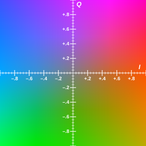
This matrix controls hue etc when in YIQ space, from ‘ntsc-ompuco’ that i ported
mat3 mix_mat = mat3(
    1.0, 0.0, 0.0,
    IHUE, SAT, 0.0,
    QHUE, 0.0, SAT
);I had a talk with him yesterday he told me you would need 2 passes,
The 1st pass would fill the analog array (represented as textures on GLSL) like it does in crt_ntsc.c
Then a 2nd pass that does what crt_core.c does which is filtering/decoding the texture in 1st pass. This is a full CVBS signal emulation more accurate than blargg but a lot slower.
Actually almost translated crt_ntsc.c to GLSL code lol. Reading the code i understood that it does a full emulation taking in to account all NTSC timings.
Hey, this kind of interest is great! Don’t let the “slower” part discourage you. Sometimes the world just needs people to build things and the results will come later.
Remember Moore’s law. The performance will come and the wait may not be that long. Also as you delve into the code you might find pathways for more efficiency and optimization. Take BSNES as an example.
You’re a very talented programmer.
Blargg does things in a pretty beautiful way but it’s not perfect. There are some inherent flaws like with all things, for example it adds white dots when you increase the Fringing.
By the way, I don’t know if anyone else has noticed this but in the Blargg_SNES Video Filter presets Fringing and Artifacts refer to the opposite effects in CRT-Guest-Advanced-NTSC or the NTSC Adaptive Shaders.
Not sure who’s correct or where the discrepancy originated but that’s some RetroArch trivia for ya.
I am interested to see how a TV works, before had no clue. What they did to put color in (before) monochrome signal was really genious. About the shader, the amount of loops there would run at 0.5 fps lol. Need to convert code, then read what it does, do it in another way, more GPU friendly. In other words do a loose translation. Or else push the code as it is and leave it there…
About the artifacts, they are generated by bandwidth limitations to fit the color in there, for example a transition of very bright saturated colors, the bandwidth can’t hold both Y and C at full, it kind of overflows and returns funky pixels. I am very interested to emulate that
Here is crt_core_c translated to Javascript which should be the easiest language for a human being
to understand (translated to Javascript first that is closer to C then started converting to GLSL)
cpp
#include <stdlib.h>
#include <string.h>

#define POSMOD(x, n)     (((x) % (n) + (n)) % (n))
static int sigpsin15[18] = {
    0x0000,
    0x0c88,0x18f8,0x2528,0x30f8,0x3c50,0x4718,0x5130,0x5a80,
    0x62f0,0x6a68,0x70e0,0x7640,0x7a78,0x7d88,0x7f60,0x8000,
    0x7f60
};
static int
sintabil8(int n)
{
    int f, i, a, b;

    f = n >> 0 & 0xff;
    i = n >> 8 & 0xff;
    a = sigpsin15[i];
    b = sigpsin15[i + 1];
    return (a + ((b - a) * f >> 8));
}

function crt_sincos14(s, c, n) {
    var h;
    n &= T14_MASK;
    h = n & ((T14_2PI >> 1) - 1);
    if (h > ((T14_2PI >> 2) - 1)) {
        c = -sintabil8(h - (T14_2PI >> 2));
        s = sintabil8((T14_2PI >> 1) - h);
    } else {
        c = sintabil8((T14_2PI >> 2) - h);
        s = sintabil8(h);
    }
    if (n > ((T14_2PI >> 1) - 1)) {
        c = -c;
        s = -s;
    }
}

function crt_bpp4fmt(format) {
    switch (format) {
        case CRT_PIX_FORMAT_RGB:
        case CRT_PIX_FORMAT_BGR:
            return 3;
        case CRT_PIX_FORMAT_ARGB:
        case CRT_PIX_FORMAT_RGBA:
        case CRT_PIX_FORMAT_ABGR:
        case CRT_PIX_FORMAT_BGRA:
            return 4;
        default:
            return 0;
    }
}

var USE_CONVOLUTION = 0;
var USE_7_SAMPLE_KERNEL = 1;
var USE_6_SAMPLE_KERNEL = 0;
var USE_5_SAMPLE_KERNEL = 0;
if (CRT_CC_SAMPLES != 4) {
    USE_CONVOLUTION = 0;
}
if (USE_CONVOLUTION) {
    var eqY = {
        h: [0, 0, 0, 0, 0, 0, 0]
    };
    var eqI = {
        h: [0, 0, 0, 0, 0, 0, 0]
    };
    var eqQ = {
        h: [0, 0, 0, 0, 0, 0, 0]
    };

    function init_eq(f, f_lo, f_hi, rate, g_lo, g_mid, g_hi) {
        f.h = [0, 0, 0, 0, 0, 0, 0];
    }
    function reset_eq(f) {
        f.h = [0, 0, 0, 0, 0, 0, 0];
    }
    function eqf(f, s) {
        var i;
        var h = f.h;
        for (i = 6; i > 0; i--) {
            h[i] = h[i - 1];
        }
        h[0] = s;
        if (USE_7_SAMPLE_KERNEL) {
            return (s + h[6] + ((h[1] + h[5]) * 4) + ((h[2] + h[4]) * 7) + (h[3] * 8)) >> 5;
        } else if (USE_6_SAMPLE_KERNEL) {
            return (s + h[5] + 3 * (h[1] + h[4]) + 4 * (h[2] + h[3])) >> 4;
        } else if (USE_5_SAMPLE_KERNEL) {
            return (s + h[4] + ((h[1] + h[2] + h[3]) << 1)) >> 3;
        } else {
            return (s + h[3] + h[1] + h[2]) >> 2;
        }
    }
} else {
    var HISTLEN = 3;
    var HISTOLD = (HISTLEN - 1);
    var HISTNEW = 0;
    var EQ_P = 16;
    var EQ_R = (1 << (EQ_P - 1));

    var eqY = {
        lf: 0,
        hf: 0,
        g: [0, 0, 0],
        fL: [0, 0, 0, 0],
        fH: [0, 0, 0, 0],
        h: [0, 0, 0]
    };
    var eqI = {
        lf: 0,
        hf: 0,
        g: [0, 0, 0],
        fL: [0, 0, 0, 0],
        fH: [0, 0, 0, 0],
        h: [0, 0, 0]
    };
    var eqQ = {
        lf: 0,
        hf: 0,
        g: [0, 0, 0],
        fL: [0, 0, 0, 0],
        fH: [0, 0, 0, 0],
        h: [0, 0, 0]
    };

    function init_eq(f, f_lo, f_hi, rate, g_lo, g_mid, g_hi) {
        var sn, cs;
        f.g = [g_lo, g_mid, g_hi];
        crt_sincos14(sn, cs, T14_PI * f_lo / rate);
        if (EQ_P >= 15) {
            f.lf = 2 * (sn << (EQ_P - 15));
        } else {
            f.lf = 2 * (sn >> (15 - EQ_P));
        }
        crt_sincos14(sn, cs, T14_PI * f_hi / rate);
        if (EQ_P >= 15) {
            f.hf = 2 * (sn << (EQ_P - 15));
        } else {
            f.hf = 2 * (sn >> (15 - EQ_P));
        }
    }
    function reset_eq(f) {
        f.fL = [0, 0, 0, 0];
        f.fH = [0, 0, 0, 0];
        f.h = [0, 0, 0];
    }
    function eqf(f, s) {
        var i, r = [0, 0, 0];
        f.fL[0] += (f.lf * (s - f.fL[0]) + EQ_R) >> EQ_P;
        f.fH[0] += (f.hf * (s - f.fH[0]) + EQ_R) >> EQ_P;
        for (i = 1; i < 4; i++) {
            f.fL[i] += (f.lf * (f.fL[i - 1] - f.fL[i]) + EQ_R) >> EQ_P;
            f.fH[i] += (f.hf * (f.fH[i - 1] - f.fH[i]) + EQ_R) >> EQ_P;
        }
        r[0] = f.fL[3];
        r[1] = f.fH[3] - f.fL[3];
        r[2] = f.h[HISTOLD] - f.fH[3];
        for (i = 0; i < 3; i++) {
            r[i] = (r[i] * f.g[i]) >> EQ_P;
        }
        for (i = HISTOLD; i > 0; i--) {
            f.h[i] = f.h[i - 1];
        }
        f.h[HISTNEW] = s;
        return (r[0] + r[1] + r[2]);
    }
}

function crt_resize(v, w, h, f, out) {
    v.outw = w;
    v.outh = h;
    v.out_format = f;
    v.out = out;
}
function crt_reset(v) {
    v.hue = 0;
    v.saturation = 10;
    v.brightness = 0;
    v.contrast = 180;
    v.black_point = 0;
    v.white_point = 100;
    v.hsync = 0;
    v.vsync = 0;
}
function crt_init(v, w, h, f, out) {
    v = {
        outw: 0,
        outh: 0,
        out_format: 0,
        out: [],
        hue: 0,
        saturation: 0,
        brightness: 0,
        contrast: 0,
        black_point: 0,
        white_point: 0,
        hsync: 0,
        vsync: 0,
        rn: 194,
        analog: [],
        inp: [],
        ccf: [],
        scanlines: 0,
        blend: false
    };
    crt_resize(v, w, h, f, out);
    crt_reset(v);
    v.rn = 194;

    function kHz2L(kHz) {
        return CRT_HRES * (kHz * 100) / L_FREQ;
    }

    if (CRT_CC_SAMPLES == 4) {
        init_eq(eqY, kHz2L(1500), kHz2L(3000), CRT_HRES, 65536, 8192, 9175);
        init_eq(eqI, kHz2L(80),   kHz2L(1150), CRT_HRES, 65536, 65536, 1311);
        init_eq(eqQ, kHz2L(80),   kHz2L(1000), CRT_HRES, 65536, 65536, 0);
    } else if (CRT_CC_SAMPLES == 5) {
        init_eq(eqY, kHz2L(1500), kHz2L(3000), CRT_HRES, 65536, 12192, 7775);
        init_eq(eqI, kHz2L(80),   kHz2L(1150), CRT_HRES, 65536, 65536, 1311);
        init_eq(eqQ, kHz2L(80),   kHz2L(1000), CRT_HRES, 65536, 65536, 0);
    } else {
        throw new Error("NTSC-CRT currently only supports 4 or 5 samples per chroma period.");
    }
}
function crt_demodulate(v, noise) {
    var out = [];
    var i, j, line, rn;
    var sig;
    var s = 0;
    var field, ratio;
    var ccr;
    var huesn, huecs;
    var xnudge = -3, ynudge = 3;
    var bright = v.brightness - (BLACK_LEVEL + v.black_point);
    var bpp, pitch;
    var prev_e, max_e;
    bpp = crt_bpp4fmt(v.out_format);
    if (bpp == 0) {
        return;
    }
    pitch = v.outw * bpp;
    crt_sincos14(huesn, huecs, ((v.hue % 360) + 33) * 8192 / 180);
    huesn >>= 11;
    huecs >>= 11;
    rn = v.rn;
    for (i = 0; i < CRT_INPUT_SIZE; i++) {
        var nn = noise;
        rn = (214019 * rn + 140327895);
        s = v.analog[i] + (((((rn >> 16) & 0xff) - 0x7f) * nn) >> 8);
        if (s >  127) { s =  127; }
        if (s < -127) { s = -127; }
        v.inp[i] = s;
    }
    v.rn = rn;
    for (i = -CRT_VSYNC_WINDOW; i < CRT_VSYNC_WINDOW; i++) {
        line = POSMOD(v.vsync + i, CRT_VRES);
        sig = v.inp + line * CRT_HRES;
        s = 0;
        for (j = 0; j < CRT_HRES; j++) {
            s += sig[j];
            if (s <= (CRT_VSYNC_THRESH * SYNC_LEVEL)) {
                break;
            }
        }
    }
    field = (j > (CRT_HRES / 2));
    v.vsync = -3;
    field = (field * (ratio / 2));
    for (line = CRT_TOP; line < CRT_BOT; line++) {
        var pos, ln;
        var scanL, scanR, dx;
        var L, R;
        var cL, cR;
        var wave = [];
        var dci, dcq;
        var xpos, ypos;
        var beg, end;
        var phasealign;
        beg = (line - CRT_TOP + 0) * (v.outh + v.v_fac) / CRT_LINES + field;
        end = (line - CRT_TOP + 1) * (v.outh + v.v_fac) / CRT_LINES + field;
        if (beg >= v.outh) { continue; }
        if (end > v.outh) { end = v.outh; }
        ln = (POSMOD(line + v.vsync, CRT_VRES)) * CRT_HRES;
        sig = v.inp + ln + v.hsync;
        s = 0;
        for (i = -CRT_HSYNC_WINDOW; i < CRT_HSYNC_WINDOW; i++) {
            s += sig[SYNC_BEG + i];
            if (s <= (CRT_HSYNC_THRESH * SYNC_LEVEL)) {
                break;
            }
        }
        v.hsync = 0;
        xpos = POSMOD(AV_BEG + v.hsync + xnudge, CRT_HRES);
        ypos = POSMOD(line + v.vsync + ynudge, CRT_VRES);
        pos = xpos + ypos * CRT_HRES;
        ccr = v.ccf[ypos % CRT_CC_VPER];
        sig = v.inp + ln + (v.hsync - (v.hsync % CRT_CC_SAMPLES));
        for (i = CB_BEG; i < CB_BEG + (CB_CYCLES * CRT_CB_FREQ); i++) {
            var p, n;
            p = ccr[i % CRT_CC_SAMPLES] * 127 / 128;
            n = sig[i];
            ccr[i % CRT_CC_SAMPLES] = p + n;
        }
        phasealign = POSMOD(v.hsync, CRT_CC_SAMPLES);
        if (CRT_CC_SAMPLES == 4) {
            dci = ccr[(phasealign + 1) & 3] - ccr[(phasealign + 3) & 3];
            dcq = ccr[(phasealign + 2) & 3] - ccr[(phasealign + 0) & 3];
            wave[0] = ((dci * huecs - dcq * huesn) >> 4) * v.saturation;
            wave[1] = ((dcq * huecs + dci * huesn) >> 4) * v.saturation;
            wave[2] = -wave[0];
            wave[3] = -wave[1];
        } else if (CRT_CC_SAMPLES == 5) {
            var dciA, dciB;
            var dcqA, dcqB;
            var ang = (v.hue % 360);
            var off180 = CRT_CC_SAMPLES / 2;
            var off90 = CRT_CC_SAMPLES / 4;
            var peakA = phasealign + off90;
            var peakB = phasealign + 0;
            dciA = dciB = dcqA = dcqB = 0;
            dciA = ccr[(peakA) % CRT_CC_SAMPLES];
            dciB = (ccr[(peakA + off180) % CRT_CC_SAMPLES]
                  + ccr[(peakA + off180 + 1) % CRT_CC_SAMPLES]) / 2;
            dcqA = ccr[(peakB + off180) % CRT_CC_SAMPLES];
            dcqB = ccr[(peakB) % CRT_CC_SAMPLES];
            dci = dciA - dciB;
            dcq = dcqA - dcqB;
            for (i = 0; i < CRT_CC_SAMPLES; i++) {
                var sn, cs;
                crt_sincos14(sn, cs, ang * 8192 / 180);
                waveI[i] = ((dci * cs + dcq * sn) >> 15) * v.saturation;
                crt_sincos14(sn, cs, (ang + 90) * 8192 / 180);
                waveQ[i] = ((dci * cs + dcq * sn) >> 15) * v.saturation;
                ang += (360 / CRT_CC_SAMPLES);
            }
        }
        sig = v.inp + pos;
        dx = ((AV_LEN - 1) << 12) / v.outw;
        scanL = 0;
        scanR = (AV_LEN - 1) << 12;
        L = 0;
        R = AV_LEN;
        reset_eq(eqY);
        reset_eq(eqI);
        reset_eq(eqQ);
        for (i = L; i < R; i++) {
            out[i].y = eqf(eqY, sig[i] + bright) << 4;
            out[i].i = eqf(eqI, sig[i] * waveI[i % CRT_CC_SAMPLES] >> 9) >> 3;
            out[i].q = eqf(eqQ, sig[i] * waveQ[i % CRT_CC_SAMPLES] >> 9) >> 3;
        }
        cL = v.out + (beg * pitch);
        cR = cL + pitch;
        for (pos = scanL; pos < scanR && cL < cR; pos += dx) {
            var y, i, q;
            var r, g, b;
            var aa, bb;
            R = pos & 0xfff;
            L = 0xfff - R;
            s = pos >> 12;
            yiqA = out + s;
            yiqB = out + s + 1;
            y = ((yiqA.y * L) >>  2) + ((yiqB.y * R) >>  2);
            i = ((yiqA.i * L) >> 14) + ((yiqB.i * R) >> 14);
            q = ((yiqA.q * L) >> 14) + ((yiqB.q * R) >> 14);
            r = (((y + 3879 * i + 2556 * q) >> 12) * v.contrast) >> 8;
            g = (((y - 1126 * i - 2605 * q) >> 12) * v.contrast) >> 8;
            b = (((y - 4530 * i + 7021 * q) >> 12) * v.contrast) >> 8;
            if (r < 0) r = 0;
            if (g < 0) g = 0;
            if (b < 0) b = 0;
            if (r > 255) r = 255;
            if (g > 255) g = 255;
            if (b > 255) b = 255;
            if (v.blend) {
                aa = (r << 16 | g << 8 | b);
                switch (v.out_format) {
                    case CRT_PIX_FORMAT_RGB:
                    case CRT_PIX_FORMAT_RGBA:
                        bb = cL[0] << 16 | cL[1] << 8 | cL[2];
                        break;
                    case CRT_PIX_FORMAT_BGR:
                    case CRT_PIX_FORMAT_BGRA:
                        bb = cL[2] << 16 | cL[1] << 8 | cL[0];
                        break;
                    case CRT_PIX_FORMAT_ARGB:
                        bb = cL[1] << 16 | cL[2] << 8 | cL[3];
                        break;
                    case CRT_PIX_FORMAT_ABGR:
                        bb = cL[3] << 16 | cL[2] << 8 | cL[1];
                        break;
                    default:
                        bb = 0;
                        break;
                }
                bb = (((aa & 0xfefeff) >> 1) + ((bb & 0xfefeff) >> 1));
            } else {
                bb = (r << 16 | g << 8 | b);
            }
            switch (v.out_format) {
                case CRT_PIX_FORMAT_RGB:
                case CRT_PIX_FORMAT_RGBA:
                    cL[0] = bb >> 16 & 0xff;
                    cL[1] = bb >>  8 & 0xff;
                    cL[2] = bb >>  0 & 0xff;
                    break;
                case CRT_PIX_FORMAT_BGR:
                case CRT_PIX_FORMAT_BGRA:
                    cL[0] = bb >>  0 & 0xff;
                    cL[1] = bb >>  8 & 0xff;
                    cL[2] = bb >> 16 & 0xff;
                    break;
                case CRT_PIX_FORMAT_ARGB:
                    cL[1] = bb >> 16 & 0xff;
                    cL[2] = bb >>  8 & 0xff;
                    cL[3] = bb >>  0 & 0xff;
                    break;
                case CRT_PIX_FORMAT_ABGR:
                    cL[1] = bb >>  0 & 0xff;
                    cL[2] = bb >>  8 & 0xff;
                    cL[3] = bb >> 16 & 0xff;
                    break;
                default:
                    break;
            }
            cL += bpp;
        }
        for (s = beg + 1; s < (end - v.scanlines); s++) {
            v.out[s * pitch] = v.out[(s - 1) * pitch];
        }
    }
}Just to make sure we’re on the same page, I was trying to encourage you to pursue the part of converting the crt_ntsc.c and crt_core.c into GLSL as you mentioned you were doing. I’m especially intrigued by this part:
Maybe you can push the code as it is first so that we can have an accurate reference, then work on the optimized version. In the future, hardware should be able to run both easily. Even if it’s 0.5 fps now, just remember Moore’s law. We can’t always have instant gratification and get to play with or enjoy everything we’ve worked hard for but some future generation might still be thankful for the path we have laid.
Maybe after going through the process you might have a much better understanding of things and that might serve to grow you in ways that you might have never imagined?
These particular artifacts that I’m referring to I can confidently say that I’ve never seen anything like them on a real CRT and they’re a tad distracting and limit me from using the artifact feature in the first place. I can provide screenshots but it can be commonly seen in the edges of the text on the signs at the beginning of levels in Bonk’s Revenge.
The signs are a light brown while the text is a very dark brown, where do white dots fit in to that picture at the intersection between the dark brown and the light brown?
I’m more used to and comfortable seeing the blue/red and a mixture of the two superimposed on white/grey edges and sometimes creating rainbow effects.
Here is the glsl code so far, 1st pass (crt_template.c) Nothing working but anyway that’s the progress translating to GLSL. All 1st pass code is coverted to be readable on GL
  #version 130

#if defined(VERTEX)

#if __VERSION__ >= 130
#define COMPAT_VARYING out
#define COMPAT_ATTRIBUTE in
#define COMPAT_TEXTURE texture
#else
#define COMPAT_VARYING varying
#define COMPAT_ATTRIBUTE attribute
#define COMPAT_TEXTURE texture2D
#endif

#ifdef GL_ES
#define COMPAT_PRECISION mediump
#else
#define COMPAT_PRECISION
#endif

COMPAT_ATTRIBUTE vec4 VertexCoord;
COMPAT_ATTRIBUTE vec4 COLOR;
COMPAT_ATTRIBUTE vec4 TexCoord;
COMPAT_VARYING vec4 COL0;
COMPAT_VARYING vec4 TEX0;

vec4 _oPosition1;
uniform mat4 MVPMatrix;
uniform COMPAT_PRECISION int FrameDirection;
uniform COMPAT_PRECISION int FrameCount;
uniform COMPAT_PRECISION vec2 OutputSize;
uniform COMPAT_PRECISION vec2 TextureSize;
uniform COMPAT_PRECISION vec2 InputSize;

// compatibility #defines
#define vTexCoord TEX0.xy
#define SourceSize vec4(TextureSize, 1.0 / TextureSize) //either TextureSize or InputSize
#define OutSize vec4(OutputSize, 1.0 / OutputSize)

void main()
{
    gl_Position = MVPMatrix * VertexCoord;
    TEX0.xy = TexCoord.xy;
}

#elif defined(FRAGMENT)

#if __VERSION__ >= 130
#define COMPAT_VARYING in
#define COMPAT_TEXTURE texture
out vec4 FragColor;
#else
#define COMPAT_VARYING varying
#define FragColor gl_FragColor
#define COMPAT_TEXTURE texture2D
#endif

#ifdef GL_ES
#ifdef GL_FRAGMENT_PRECISION_HIGH
precision highp float;
#else
precision mediump float;
#endif
#define COMPAT_PRECISION mediump
#else
#define COMPAT_PRECISION
#endif

uniform COMPAT_PRECISION int FrameDirection;
uniform COMPAT_PRECISION int FrameCount;
uniform COMPAT_PRECISION vec2 OutputSize;
uniform COMPAT_PRECISION vec2 TextureSize;
uniform COMPAT_PRECISION vec2 InputSize;
uniform sampler2D Texture;
COMPAT_VARYING vec4 TEX0;

// compatibility #defines
#define Source Texture
#define vTexCoord TEX0.xy

#define SourceSize vec4(TextureSize, 1.0 / TextureSize) //either TextureSize or InputSize
#define OutSize vec4(OutputSize, 1.0 / OutputSize)

#ifdef PARAMETER_UNIFORM
uniform COMPAT_PRECISION float GLITCH;

#else
#define GLITCH 0.1
#endif


#define CRT_VRES        262                       // vertical resolution

const int Q_OFFSET = -90;   // in degrees
// burst hue offset
const int HUE_OFFSET = -60;  // in degrees
const int CRT_CC_SAMPLES = 4; // samples per chroma period (samples per 360 deg)
const int CRT_CC_VPER = 2; // vertical period in which the artifacts repeat
const int CRT_CC_LINE = 2275;
// NOTE, in general, increasing CRT_CB_FREQ reduces blur and bleed
    const int CRT_CB_FREQ = 4; // carrier frequency relative to sample rate
const int CRT_HRES = CRT_CC_LINE * CRT_CB_FREQ / 10; // horizontal res, 910 total
// line duration should be ~63500 ns
const int FP_ns = 1500;      // front porch
const int SYNC_ns = 4700;      // sync tip
const int BW_ns = 600;       // breezeway
const int CB_ns = 2500;      // color burst
const int BP_ns = 1600;      // back porch
const int HB_ns = FP_ns + SYNC_ns + BW_ns + CB_ns + BP_ns; // hblank 10900
const int AV_ns = 52600;     // active video
const int LINE_ns = FP_ns + SYNC_ns + BW_ns + CB_ns + BP_ns + AV_ns; // 63500 total

bool CRT_DO_BANDLIMITING = true;    // enable/disable bandlimiting when encoding
const int EXP_P = 11;
const int EXP_ONE = (1 << EXP_P);  // 2048 (1*2^11)
const int EXP_MASK = (EXP_ONE - 1);  //2047
const int EXP_PI = 6434;
const int CRT_TOP = 21;     // first line with active video
const int CRT_BOT = 261;    // final line with active video
const int CRT_LINES = CRT_BOT - CRT_TOP; // number of active video lines
// frequencies for bandlimiting
const int L_FREQ = 1431818; // full line
const int Y_FREQ = 420000;  // Luma   (Y) 4.2  MHz
const int I_FREQ = 150000;  // Chroma (I) 1.5  MHz
const int Q_FREQ = 55000;   // Chroma (Q) 0.55 MHz
   const int hue = 0;        // 0-359
const int xoffset = 0;    // x offset in sample space. 0 is minimum value
const int yoffset = 0;    // y offset in # of lines. 0 is minimum value
   const int dot_crawl_offset = 0; // 0-5
const int BLANK_LEVEL = 0;
const int SYNC_LEVEL = -40;
const int LINE_BEG = 0;
const int CRT_INPUT_SIZE = CRT_HRES * CRT_VRES;

// define line ranges in which sync is generated
// the numbers are inclusive
// Make sure these numbers fit in (0, CRT_VRES)
const int SYNC_REGION_LO = 3;
const int SYNC_REGION_HI = 6;
// same as above but for equalizing pulses
const int EQU_REGION_A_LO = 0;
const int EQU_REGION_A_HI = 2;
const int EQU_REGION_B_LO = 7;
const int EQU_REGION_B_HI = 9;
// somewhere between 7 and 12 cycles
const int CB_CYCLES = 10;
const int BURST_LEVEL = 20;

const int CRT_PIX_FORMAT_RGB = 0;  // 3 bytes per pixel [R,G,B, R,G,B, R,G,B..]
const int CRT_PIX_FORMAT_BGR = 1;  // 3 bytes per pixel [B,G,R, B,G,R, B,G,R..]
const int CRT_PIX_FORMAT_ARGB = 2;  // 4 bytes per pixel [A,R,G,B, A,R,G,B...]
const int CRT_PIX_FORMAT_RGBA = 3;  // 4 bytes per pixel [R,G,B,A, R,G,B,A...]
const int CRT_PIX_FORMAT_ABGR = 4;  // 4 bytes per pixel [A,B,G,R, A,B,G,R...]
const int CRT_PIX_FORMAT_BGRA = 5;  // 4 bytes per pixel [B,G,R,A, B,G,R,A...]
    int format = 0;     // pix format (one of the CRT_PIX_FORMATs in crt_core.h)

const int black_point = 0;
const int white_point = 0;
const IRE_MAX = 110;   // max value is max value of signed char
const IRE_MIN = 0;     // min value is min value of signed char
const WHITE_LEVEL = 100;


// convert nanosecond offset to its corresponding point on the sampled line
int ns2pos (int ns) { return (ns * CRT_HRES / LINE_ns);}   // ns * 0.0143307
// AV_LEN 753
// AV_LEN 753

int SYNC_BEG = ns2pos(FP_ns);   //21
int BW_BEG = ns2pos(FP_ns + SYNC_ns);  //88
int CB_BEG = ns2pos(FP_ns + SYNC_ns + BW_ns);  //97
int AV_BEG = ns2pos(HB_ns);  // 156
int field = 0;
int AV_LEN = ns2pos(AV_ns);   //753
int iirs_initialized = 0; // internal state

int EXP_MUL(int x, int y) {
    return (x * y) >> EXP_P; }
int EXP_DIV(int x, int y) {
    return (x << EXP_P) / y; }
int[5] e11 = int[](
    EXP_ONE,        // 2048
    5567,  // e
    15133, // e^2
    41135, // e^3
    111817 // e^4
);

int expx(int n){
    bool neg;
    int idx, res;
    int nxt, acc, del;
    int i;
    if (n == 0) {
        return EXP_ONE;  // 2048
        }
    neg = n < 0; // neg is 1 if n<0

    if (neg) {
        n = -n;  // convert n to positive number
    }
    idx = n >> EXP_P;
    res = EXP_ONE;

    for (i = 0; i < idx / 4; i++) {
        res = EXP_MUL(res, e11[4]);
    }
    idx &= 3;

    if (idx > 0) {
        res = EXP_MUL(res, e11[idx]);
    }
    n &= EXP_MASK;
    nxt = EXP_ONE;
    acc = 0;
    del = 1;

    for (i = 1; i < 17; i++) {

        if (del < nxt || nxt > 0 || del > 0) {

        acc += nxt / del;
        nxt = EXP_MUL(nxt, n);
        del *= i;

        }
    }
    res = EXP_MUL(res, acc);

    if (neg) {
        res = EXP_DIV(EXP_ONE, res);
    }
    return res;
};

// IIR lowpass filter for bandlimiting YIQ
 int[2] iirY = int[](0,0); // c,h (history)
 int[2] iirI = int[](0,0); // c,h (history)
 int[2] iirQ = int[](0,0); // c,h (history)

// freq  - total bandwidth
// limit - max frequency
//
int init_iir (int f, int freq, int limit) {
    int rate; // cycles/pixel rate
    return  EXP_ONE - expx(-((EXP_PI << 9) / rate));  // 2048 - expx(-6434 * 512/rate)
};

int reset_iir (int f) {
    return 0;
};

// hi-pass for debugging
int iirf (int c, int h, int s) {
    if (CRT_DO_BANDLIMITING) {
        c += EXP_MUL(s - h, c);
        return h;

    } else {
        return s;
    }
};

const int T14_2PI = 16384;
const int T14_MASK = (T14_2PI - 1);
const int T14_PI = (T14_2PI / 2);


const int[18] sigpsin15 = int[]( // significant points on sine wave (15-bit)
    0x0000,
    0x0c88,0x18f8,0x2528,0x30f8,0x3c50,0x4718,0x5130,0x5a80,
    0x62f0,0x6a68,0x70e0,0x7640,0x7a78,0x7d88,0x7f60,0x8000,
    0x7f60
);


int sintabil8(int n)
{
    int f, i, a, b;

    // looks scary but if you don't change T14_2PI
    // it won't cause out of bounds memory reads
    //
    f = n >> 0 & 0xff;
    i = n >> 8 & 0xff;
    a = sigpsin15[i];
    b = sigpsin15[i + 1];
    return (a + ((b - a) * f >> 8));
}

// BIT SHIFTING
// X >> 1   EQUALS TO X/2
// X >> 2   EQUALS TO X/4
// X << 1   EQUALS TO X*2
// X << 2   EQUALS TO X*4

ivec2 crt_sincos14(int s, int c, int n)
{
    int h;

    n &= T14_MASK;
    h = n & ((T14_2PI/2) - 1);

    if (h > ((T14_2PI/4) - 1)) {
        c = -sintabil8(h - (T14_2PI/4));
        s = sintabil8((T14_2PI/2) - h);
    } else {
        c = sintabil8((T14_2PI/4) - h);
        s = sintabil8(h);
    }
    if (n > ((T14_2PI/2) - 1)) {
        c = -c;
        s = -s;
    }
    return ivec2(s,c);
}

int crt_bpp4fmt(int format)
{
    if (format == 0 || format == 1) return 3;
    else if (format == 2 || format == 3 || format == 4|| format == 5) return 4;

}

// s is NTSC_SETTINGS IN TEMPLATE.H
// v IS CRT IN CORE.H

//////////////////////////////////////////////////////////////////////////////////////
//////////////////////////////////////////////////////////////////////////////////////
////////////////////////////// START MODULATION //////////////////////////////////////
//////////////////////////////////////////////////////////////////////////////////////
//////////////////////////////////////////////////////////////////////////////////////
//////////////////////////////////////////////////////////////////////////////////////
//////////////////////////////////////////////////////////////////////////////////////
//////////////////////////////////////////////////////////////////////////////////////

void crt_modulate(int v, int s) {
    int x, y, xo, yo;
    int destw = 753;  //AV_LEN
    int desth = 236; //((CRT_LINES * 64500) >> 16)
    int[CRT_CC_VPER*CRT_CC_SAMPLES] iccf    ;  // 4x2
    int[CRT_CC_VPER*CRT_CC_SAMPLES] ccmodI  ;
    int[CRT_CC_VPER*CRT_CC_SAMPLES] ccmodQ  ;
    int[CRT_CC_VPER*CRT_CC_SAMPLES] ccburst ;

struct Data
{
  int x;
  int y;
};

//Data iccf = Data(y,x,x,x,
                // y,x,x,x);
// just an idea to convert that 2D arrays

    int sn, cs, n, ph;
    int bpp;

    if (iirs_initialized == 0) {
        init_iir(iirY[1], L_FREQ, Y_FREQ);
        init_iir(iirI[1], L_FREQ, I_FREQ);
        init_iir(iirQ[1], L_FREQ, Q_FREQ);
        iirs_initialized = 1;
    }

    if (desth > 236) desth = 236;


 // y 0 to 2
    for (y = 0; y < 2; y++) {     //CRT_CC_VPER
 // y * 180'
        int vert = (y + dot_crawl_offset)*180; // 360/CRT_CC_VPER
// x 0 to 4
            for (x = 0; x < 4; x++) {   // CRT_CC_SAMPLES
// step is 90'
                int step = 90;  // 360/CRT_CC_SAMPLES
                n = vert + hue + x * step;

                crt_sincos14(sn, cs, (n - step + HUE_OFFSET) * 8192 / 180);
            ccburst[y+x] = sn >> 10;                //CHECK FOR ERRORS ON DEFINITION OF ARRAYS AT FUNCTION START

                crt_sincos14(sn, cs, n * 8192 / 180);
            ccmodI[y+x] = sn >> 10;                 //CHECK FOR ERRORS ON DEFINITION OF ARRAYS AT FUNCTION START

                crt_sincos14(sn, cs, (n + Q_OFFSET) * 8192 / 180);
            ccmodQ[y+x] = sn >> 10;                 //CHECK FOR ERRORS ON DEFINITION OF ARRAYS AT FUNCTION START
            }
        }

    bpp = crt_bpp4fmt(format);

    xo = 156;
    //AV_BEG  + xoffset + (AV_LEN    - destw) / 2
    yo = 23;
    // 21+(240-236)/2
    //CRT_TOP + yoffset + (CRT_LINES - desth) / 2

// use field and frame variables as you'd like here
// to determine starting phases, etc.
//
    //field &= 1;
    //frame &= 1;

// align signal
    xo = xo - (xo % 4); // xo mod CRT_CC_SAMPLES

//int[CRT_INPUT_SIZE] analog; // new Array(CRT_INPUT_SIZE).fill(0);
int[238420] analog;   // 910 * 262 (HRES*VRES) actually screen pixels

for (n=0; n<262; n++) {     // CRT_VRES

        // filling line with pixels vertically
        int[238420] line = analog[n*910]; // 910*262

        int t = 0;  //TIME


  // n is 0 to 2 or 7 to 9
if ((n >= EQU_REGION_A_LO && n <= EQU_REGION_A_HI) || (n >= EQU_REGION_B_LO && n <= EQU_REGION_B_HI)) {
            // equalizing pulses - small blips of sync, mostly blank
            while (t < (4   * 910 / 100)) line[t++] = SYNC_LEVEL;
            while (t < (50  * 910 / 100)) line[t++] = BLANK_LEVEL;
            while (t < (54  * 910 / 100)) line[t++] = SYNC_LEVEL;
            while (t < (100 * 910 / 100)) line[t++] = BLANK_LEVEL;

        }

        else if (n >= SYNC_REGION_LO && n <= SYNC_REGION_HI) {
            int[4] even = int[]( 46, 50, 96, 100 );
            int[4] odd  = int[](  4, 50, 96, 100 );
            int[4] offs = even;
                if (field == 1) {
                offs = odd;
                }
            // vertical sync pulse - small blips of blank, mostly sync
            while (t < (offs[0] * CRT_HRES / 100)) line[t++] = SYNC_LEVEL;
            while (t < (offs[1] * CRT_HRES / 100)) line[t++] = BLANK_LEVEL;
            while (t < (offs[2] * CRT_HRES / 100)) line[t++] = SYNC_LEVEL;
            while (t < (offs[3] * CRT_HRES / 100)) line[t++] = BLANK_LEVEL;

        } else {
            int cb;
            // video line
            // SYNC_BEG
            while (t < 21) line[t++] = BLANK_LEVEL; // FP
            // BW_BEG
            while (t < 88)   line[t++] = SYNC_LEVEL;  // SYNC
            // AV_BEG
            while (t < 156)   line[t++] = BLANK_LEVEL; // BW + CB + BP

            // CRT_TOP
            if (n < 21) {
                while (t < 910) line[t++] = BLANK_LEVEL;
            }
            // CB_CYCLES of color burst
            // CB_BEG = 97, CB_CYCLES = 10 * CRT_CB_FREQ = 4
            for (t = 97; t < 137); t++) {
                cb = ccburst[(n % 4) * (t % 2)];
                // BLANK_LEVEL = 0, BURST_LEVEL = 20
                line[t] = (0 + (cb * 20)) >> 5;
                iccf[((n + 3) % 4)*(t % 2)] = line[t];
                }
            }
}

        //desth 236
for (y = 0; y < 236; y++) {

        int h = int(SourceSize.y);  // CHECK?? height of image
        int w = int(SourceSize.x);  // CHECK?? width   --//--
        int field_offset;
        int sy;

        //desth 236
        field_offset = (field * h + 236) / 236 / 2;
        sy = (y * h) / desth;
        sy += field_offset;
        if (sy >= h) sy = h;
        sy *= w;
        reset_iir(iirY[1]);  //
        reset_iir(iirI[1]);  //
        reset_iir(iirQ[1]);  //
        //CRT_CC_VPER 2
        ph = (y + yo) % 2;
    for (x = 0; x < destw; x++) {
            int fy, fi, fq;
            int rA, gA, bA;
            int[3] pix;
            int ire; // composite signal
            int xoff;
            // RGB to YIQ matrix in 16.16 fixed point format
            int[9] yiqmat = int[](
                19595,  38470,  7471,   // Y
                39059, -18022, -21103,  // I
                13894, -34275,  20382);  // Q
            int data; // image data here<------- probably replace with a texture
                pix = data + ((((x * w) / destw) + sy) * bpp);
// here probably enter a texture2D(Source,uv) as pix
// with coords given above. rA, gA, bA would be pix.rgb
/*   // RGB to YIQ
            fy = (yiqmat[0] * rA + yiqmat[1] * gA + yiqmat[2] * bA) >> 14;
            fi = (yiqmat[3] * rA + yiqmat[4] * gA + yiqmat[5] * bA) >> 14;
            fq = (yiqmat[6] * rA + yiqmat[7] * gA + yiqmat[8] * bA) >> 14;

            ire = BLACK_LEVEL + black_point;
            xoff = (x + xo) % CRT_CC_SAMPLES;

            // bandlimit Y,I,Q
            fy = iirf(iirY[1], iirY[2], fy);
            fi = iirf(iirI[1], iirI[2], fi) * ccmodI[ph*xoff] >> 4;
            fq = iirf(iirQ[1], iirQ[2], fq) * ccmodQ[ph*xoff] >> 4;

            // modulate as (Y + sin(x) * I + cos(x) * Q)
            ire += (fy + fi + fq) * (WHITE_LEVEL * white_point / 100) >> 10;
            if (ire < IRE_MIN) ire = IRE_MIN;
            if (ire > IRE_MAX) ire = IRE_MAX;
            analog[(x + xo) + (y + yo) * CRT_HRES] = ire;*/

    }
// this generally does not need to be touched
/*    for (n = 0; n < CRT_CC_VPER; n++) {
        for (x = 0; x < CRT_CC_SAMPLES; x++) {
            ccf[n*x] = iccf[n*x] << 7;
  */

}
}

}


void main()
{

    // CHECK IF SHADER COMPILES, FOR ANY ERRORS ON ABOVE CODE
    vec4 ok = COMPAT_TEXTURE(Source,vTexCoord)*0.3;
    FragColor = ok;
}


#endifLooks awesome. How’s the speed so far?
Wow! That’s amazing man! I wish I could do that but my programming career stopped at learning how to create databases, draw simple shapes, and move them and make single note sounds and music out of the PC speaker using BASIC over 25 years ago!
So at least I have a modest appreciation for what coding entails and the level of talent required to create digital “things” out of nothing but concepts and ideas.
First translated everything so that it doesn’t give errors, tweaked here and there, precalculated things, next I have to read again the code and make trials. Probably will speak to the coder again for directions lol
@Cyber that took a lot of reading too, how to handle arrays, 2d arrays etc (which I have to correct at the code as [x+y * width] instead of [x * y] )


