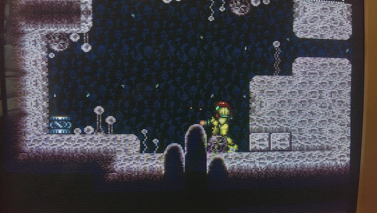
EDIT: So, I found out that the SMPTE method of calibrating a CRT involves adjusting the white level/contrast so that scanlines over the whites are equal in thickness to scanlines over the darker areas. So, ideally, a display should show very little/no scanline variability, contrary to what I initially thought.
Not really sure where to post this, but I think it’s pertinent to CRT-shaders.
Can anybody with some knowledge of how CRT monitors are calibrated shed some light on the following?
I’m curious to know the relationship between brightness, contrast, and the variability of scanline width on CRT displays.
Many shots I’ve seen of CRTs show little/no variability in scanline width across the screen. This doesn’t seem to be determined by quality/resolution, either. I’ve seen PVMs that showed almost no scanline variability, and PVMs that showed a great deal of variability.
As I understand it, a “correctly calibrated” display will set the black level (brightness) to the lowest level possible at which all detail is still visible. On a CRT, this would mean setting the brightness to the point where the darkest-colored visible lines were just barely visible, and this would make them super thin on a PVM, almost 1/4th the width of the scanlines. See this shot for reference: https://i.warosu.org/data/vr/img/0007/54/1370419191800.jpg
The correct contrast setting, to my knowledge, is the highest setting at which all detail is still visible. On a CRT this would mean that the lightest-colored visible lines would bloom to the point where the scanlines were just barely visible.
So, as a CRT got better in terms of white/black levels, and the more accurately it is calibrated, the more the scanline width varies across the screen.
Is this correct?


