
My NTSC simulation is currently all for sRGB, but adding HDR support actually is a great idea that I just haven’t gotten to doing yet. That would be able to simulate a known CRT’s color directly. I might just add that today really quick.
6 Likes
Great work @PlainOldPants! I have some assorted feedback and questions.
It looks like most of your presets have a steep low pass filter at 4.2 MHz. Wouldn’t this only be appropriate for simulating an RF connection? Composite connections could support bandwidth above 4.2 MHz. On the other hand, I suspect that most old consoles had lower bandwidth outputs even than that.
I also wonder about the correctness of simply sampling the input and applying a discrete time FIR filter. Nearest neighbor sampling should result in some aliasing. Maybe it isn’t visible, though. To avoid aliasing and try to simulate the DAC behavior, I’ve been using a continuous time FIR filter, treating the input as a piecewise constant function, and then resampling. But maybe my approach isn’t necessary.
It looks like you pack 4 samples into each vec4, so with a width of 640 there are actually 2560 samples per line. Am I reading your code correctly?
Should the primaries be corrected in the first pass? Most cores, as far as I know, just output the digital data from the console without any correction (NES can be a weird exception, obviously). I have assumed that the input should be treated as-is and any primary corrections, white balance, etc done at the end of the process.
Nicely commented code! It’s much easier to follow than some of the other code I’ve seen.
By the way, this is the comb filter that I am planning to attempt: https://patents.google.com/patent/US5663771A/en
3 Likes
The 4.2 MHz lowpass is broken. All the presets are skipping it by default.
The problem is that my 4.2 MHz filter implementation reduces the chroma saturation. In other words, it is not actually behaving according to the graph, as it’s causing the 3.58 MHz frequency (as generated by the encoding pass) to get decreased too much.
I had implemented the chroma and luma filters first, and it looked like they were working alright. The RF lowpass was added later, so I didn’t realize something was off until then.
I need to check this later, but part of the culprit could be this bug in my hamming window. The original function from my June 12th version looked like this:
vec4 window(vec4 offsets, float hammingSize) {
    const float a0 = 25.0 / 46.0;
    return a0 + (1 - a0) * cos(2 * pi * clamp(offsets / hammingSize, -0.5, 0.5));
}
The fixed version is this. This is found in my latest version.
vec4 window(vec4 offsets, float hammingSize) {
    const float a0 = 25.0 / 46.0;
    vec4 res;
    for(int i = 0; i < 4; i++) {
        res[i] = offsets[i] >= -0.5 && offsets[i] <= 0.5 ? a0 + (1 - a0) * cos(2 * pi * clamp(offsets[i] / hammingSize, -0.5, 0.5)) : 0;
    }
    return res;
}
I only remembered to paste this fixed version in the encode and decode passes, but not in the RF lowpass pass. Still, I doubt that this is the entire problem. As you said, the simple discrete time FIR filter isn’t necessarily the best choice. Until I added the RF lowpass, I had thought that I was over-sampling high enough to where this wasn’t an issue, but clearly I was not.
Based on your previous message to me in your crt-beans thread, and based on what you’re saying here, I can clearly see that you are more experienced with signal processing/filtering than I am.
About the 4.2 MHz lowpass only being applicable to RF, that’s true according to the standard. I need to check the schematic diagrams to make sure that consoles are properly skipping that lowpass when connected only over composite.
I believe I remember the SNES having different filtering for the final RF output and for the final composite output–That’s two different lowpass filters (or whatever kind of filter), where one is for composite, and the other is RF. Again, I need to check to make sure I’m remembering correctly. I do not own a real SNES.
My NES has excessively blurry RF and excessively sharp composite. If I connect the NES’s composite through my VCR to modulate it into RF so that I can connect it to my 1989 RCA CRT, I still see the grainy, sandy look of the NES’s overly sharp composite, although it’s not as horrible as the straight composite signal.
I also believe the NES’s RF modulator may be causing the NES’s chroma to get more saturated. It may also be causing the luma to create more chroma artifacts. I need to check this later.
As for my Genesis, I don’t know. At least, everyone knows that the Genesis low-passes its audio, but I suspect that they were using the same audio low-pass filter for RF and for composite. That might suggest that video goes through the same low-pass for both RF and for composite. I need to check the schematic and see.
Speaking of filtering, I just noticed this past weekend that my 1989 RCA ColorTrak is being relatively generous with its chroma lowpass/bandpass. It looks like it is not lowpassing as low as the standard Q response, but it is definitely lower than the standard I response. I’ll need to investigate.
Long story short, the answers to most of our questions about filtering are in the schematic diagrams.
I have not gotten the capacitors replaced on my consoles. This might be affecting the video filtering. My Genesis has the well-known rainbow banding issue, and I’ve heard that you can reduce it a lot by replacing capacitors. The only CRT I have that’s been serviced is the 1989 RCA one, which still has its original whitepoint intact, but has its default brightness set based on 0 IRE and its default tint and color set to make the yellow area look acceptable without accounting for 1953 NTSC primaries. Everything else that I own may have capacitor-related problems with filtering.
That is correct. The number 2560 ensures that resolutions of 256, 320, 512, and 640 all divide each pixel into an integer number of samples. I don’t remember exactly how my code works and whether it properly handles an input size that doesn’t divide 2560 evenly. I know my previous release would either crop or add pillarboxes to ensure that the sample rate was divided evenly. As a bonus, that meant that if the user had enabled cropping overscan, or if the console (such as SNES or Genesis) supported multiple resolutions, the shader would automatically detect and compensate for that.
As far as I’m aware, never. I’m sure that consoles never ever did this.
The reason why I added that was so that I could try watching YouTube videos with the shader (either using ShaderGlass or the WindowCast core; I recommend ShaderGlass for better performance), and calibrate the NTSC brightness, tint, color, and sharpness manually by eye. This is because of how consumers could’ve done anything with their knobs, and how they may have set their TV’s settings manually instead of sticking to defaults.
The Genesis/MegaDrive is the only exception I know of. The RGB analog voltages are not linearly related to their internal digital values. Different Genesis/MegaDrive models had different voltages. According to the Genesis 240p test suite, the Genesis’s black level is about 6 IRE.
In Genesis Plux GX, you get the console’s raw digital RGB values. In BlastEm, you get the analog voltages. I assume everything except BlastEm also only has the raw digital values. https://github.com/ekeeke/Genesis-Plus-GX/issues/345#issuecomment-1675678054 “Literally all I did in BlastEm was took the voltages others had measured for each of the Mode 5 RGB levels, divided by the max measured voltage and multiplied by 255. Those values are in levels in vdp.c and get used for translating palette entries. Nothing fancy at all.”
Thank you. A lot of the detailed comments in there were just to compensate for my own crappy memory and difficulties with understanding code after it’s been written (and maybe because I’m too nerdy), but I’m happy to see that all my documentation and explanations are paying off, whether it’s in the code itself, or in my detailed posts that have hardly any views/downloads. Just beware that some comments were written before I actually wrote the code and are still unchanged.
I’ll look at this in more detail later, since I’m in a bit of a hurry. It took longer than expected for me to write this.
Edit, about 2 hours later:
I’m looking over the patent now, and this paragraph in particular on page 4 (or page 10 of the PDF) sticks out to me:
“In accordance with the present invention, an adaptive comb filter for NTSC or PAL television standards has only two horizontal scan lines of delay and effectively removes the high frequency luma. The magnitude and phase of the chroma signal from the comb filter are compared to the input signal to the comb filter which has been subject to a bandpass filtering process. Unless both the magnitude and phase of the comb filter chroma signal are equal to or less than that of the bandpass filtered signal, the comb filter chroma signal is assumed to be incorrect (“illegal’) and a different comb filter is adaptively selected to legalize the chroma output signal.”
This is similar to what my latest NTSC shader is doing for its adaptive comb filter. What makes mine different is that, instead of checking whether a comb filter gives a “legal” result before falling back to another comb filter, mine compares all the comb filters to see which one is the most “legal”, even if all three are illegal. In other words, this paper’s invention puts the different comb filters in an order of priority, and always picks the highest-priority one that picks a legal result, whereas my shader assigns no priority order at all, and always picks the one that has the best result.
Another difference in my shader is that I perform a 1.3 MHz lowpass on each line, and I assume that this lower frequency range is almost entirely correct luma information. Then, when comb-filtering, the comb filter only is performed on the higher frequency information above that. This means that consecutive lines won’t get blurred together as badly. This patent instead claims that the entire luma signal needs to be comb filtered because even the lowest frequencies are allowed to contain chroma.
3 Likes
Based on your previous message to me in your crt-beans thread, and based on what you’re saying here, I can clearly see that you are more experienced with signal processing/filtering than I am.
I’m not sure about that. Unfortunately, I took compilers instead of signal processing and now I wish I had taken both.
Until I added the RF lowpass, I had thought that I was over-sampling high enough to where this wasn’t an issue, but clearly I was not.
We can do some calculations for a simple square wave, like black/white alternating pixels. A real signal would have more complicated frequency content, but this would be the worst case scenario for high frequency content. With a 640 pixel wide input and 2560 samples per line, the 5th harmonic would be the first to be reflected as aliasing, and it would be at about -14dB. With a 320 pixel wide input, the 9th harmonic would alias at -19dB. (Assuming I’ve done the math correctly.)
Some of the aliasing will be in the range that is getting attenuated by the low pass filter.
Having the number of samples be an even multiple of the input may help hide the aliasing in some cases, since some of it it will be reflected back onto the lower harmonics of the signal. It might look a little like sharpening, overemphasizing the higher frequencies.
All of this is to say that I don’t really know how much of a visual impact the aliasing will have in the end. It might be okay with this much oversampling, but the aliasing should be more significant with higher resolutions.
I believe I remember the SNES having different filtering for the final RF output and for the final composite output
It does look that way from the schematic. It looks like there is also:
- a luma trap filter
- a chroma filter for each of R-Y and B-Y before modulation
- a buffer in front of each of the RGB inputs that may affect the frequency response
Nintendo sure put a lot of components onto that board.
I have a SNES but it isn’t currently working.  I was hoping to use it for some visual comparisons.
The number 2560 ensures that resolutions of 256, 320, 512, and 640 all divide each pixel into an integer number of samples
Genesis Plus GX will output something like 384 pixels (I didn’t have the exact number in front of me right now). The main 320 pixel output doesn’t cover the whole active area. Some border padding is added. In my opinion, other cores should be doing this as well, and Ares seems to have made an effort to do this. So that might be something to consider.
I will have to take a look at your comb filter. It sounds interesting! What happens when there is input like the Genesis, which keeps a consistent phase from line to line and thus can’t be comb filtered? I haven’t been able to test that yet.
3 Likes
3840 is even better than 2560 for being an integer multiple of even weird horizontal resolutions.
On my shaders, when set up for Gen/MD, comb filters killed all of the chroma due to the fixed-phase signal, while notch filters do just fine. It’s surprisingly hard to find first-hand accounts of this, and I never heard anything about it during the CRT era, but did find this on reddit, talking about the retrotink 2X’s comb filter:
There are just some edge case exceptions for certain Genesis & 32X revisions which the 2X can’t decode the colors accurately. (in such cases a 5X is needed as you can correct it with the phase setting)
So yeah, seems like it indeed buggers the chroma completely. Apparently, some (most? all?) comb-based sets had a fallback notch filter, so maybe it switches over to that if the phase is fixed? or maybe if the chroma signal drops below a certain voltage? Dunno.
Note that most comb filters are adaptive, which means they also use a notch filter for portions of the decoding process depending on the properties of the signal.
That same page includes an excerpt from a JVC model’s owner’s manual that suggests it was a manual switch, at least for that model.
EDIT: I also recall PlainOldPants asking if anyone had done anything with overdriven electron guns that caused smearing to the right. I did a “chroma smear” shader a number of years ago that wasn’t really based on anything but my own memory of failing TVs, but the result was pretty good:

5 Likes
I was looking for something like this before
thanks! and why didnt added to https://github.com/libretro/slang-shaders yet?
1 Like
I didn’t think it warranted it, since it’s just a unidirectional blur in yiq colorspace. if it did anything super-special, I’d have put it up there.
I’ve made some random progress on my NTSC shader. Hopefully I’ll have it finished enough by the end of this month to where I’m comfortable submitting a PR to the slang-shaders repository.
- Did a better job at simulating NTSC colors. I’ve done a much better job at simulating the colors of my 1985 Toshiba Blackstripe and 1989 RCA ColorTrak, and I have made better approximations of standard NTSC color.
- Added support for comb filtering with NES and SNES, but I’m not sure if real CRTs worked this way or not.
- Added interlacing. If the vertical resolution is over 300 pixels, interlacing is enabled.
The NES simulation still needs more work. In particular, it is missing row-skew in its colors, so you won’t get a very accurate NES palette with this.
Download here: https://www.mediafire.com/file/3e652wqa2kfpxuh/p68k-fast-multipass-2025-10-07.zip/file
One of the included presets lets you do only the NTSC color correction. It contains a lot of confusing settings, but there is only one that really matters much: “Video decoder/region (see list below)”
- US consumer - Options 3 and 4 are based on real US NTSC consumer CRTs that somewhat break the NTSC standard. Option 3 gives the stronger “consumer” feel with a 9300K whitepoint, and I believe it appears in many Sony and Toshiba consumer CRTs in the US.
- Japan consumer - Option 7 is a guess at what a Japanese consumer CRT could look like.
- US or Japan PVM - Options 2 and 6 are based directly on the US and Japan standards respectively. While these were always the standard for professional NTSC CRTs, I assume it didn’t become widespread in consumer CRTs until the later half of the 90s.
5 Likes
Took it for a spin with some Genesis games, looks VERY authentic.
The comb filter stuff is neat- first time seeing those atrocious hanging dots emulated correctly. The artifacting in general looks better than any current implementation I’ve seen.
Really good stuff.
Any progress on this? 
3 Likes
Always following up your content, buddy. Even though not commenting regularly. Thank you for your amazing work, time and tenacity. Really appreciate this content related to composite video experience.
3 Likes
I have been thinking about this, and I think you are doing it correctly (if my understanding of what you are doing is correct). I wasn’t sure at first if the comb filtering would work for consoles that didn’t correctly flip the chroma phase each line (i.e. have line times of 227.5 periods of the chroma subcarrier). But, here’s my reasoning now. The key is that all sources respect the chroma subcarrier frequency but may alter the hsync or vsync intervals.
- For analog comb filters, the delay line (e.g. a glass delay line) was probably specified to have a delay time of 227.5 / 3579545 ~= 63.556 µs. The delayed value should have the opposite phase of the current value, although it will not be directly vertically adjacent if the line time is not ~63.556 µs.
- For digital comb filters, this gets trickier. I suspect that the sampling rate was locked to 4 * 3579545 Hz (at least for the early ones). If they could sync the sampling to the chroma subcarrier, this would allow easy QAM demodulation of I and Q without multiplications or trigonometric functions. The “window” into the line would be slightly shifted each time. So looking at the same index in the delayed line would again get you a value with the phase inverted, but not necessarily directly vertically adjacent. There are some extra things they would need to take into account to make this work without adding jitter or desyncing, and this purely speculation on my part.
So the tl;dr is that the delay is based on the chroma subcarrier, rather than the hsync interval as I had previously thought.
1 Like
Long time no see, Pants. IDK why I’m getting like the NTSC output on your shaders. Am I doing something wrong?
If you’re playing on NES, make sure you set your emulator’s palette to “Raw”. It should work right with Mesen or FCEUmm, and maybe Nestopia. If you’re still getting glitchy output after that, then that means I did something wrong.
Edit: Also make sure that your emulator’s own NTSC filter is turned off, so that you don’t combine two different NTSC filters together.
While I’m here, here’s an update to my latest multipass shader which now has mostly complete NES support.
https://www.mediafire.com/file/q1lsxv4t7a5y064/p68k-fast-multipass-2025-10-19.zip/file
Also read this:
2 Likes
You might be interested in the comb filter discussion here:
https://www.extron.com/article/ntscdb3
https://www.extron.com/article/ntscdb4
If you want to do adaptive comb filtering, determining the correlation between lines is what you want to do. I believe a mix of comb and notch filtering was also done by some TVs. You can do the two in parallel and mix them together. You’d need a notch filter with minimum group delay, so probably implemented only digitally in newer CRTs.
I don’t think you should take the video standards as prescriptive. They were more descriptive, to get everyone to align on the same assumptions. In this sense, it’s best not to worry too much about when exactly standards were adopted in regards to consumer equipment.
I notice you filter on the encoding. Not all systems filtered their output like this, but I think the later consoles started to (PS1?). If you separate the filtering from encoding and moving all filtering to the decode, you can avoid needing to store intermediates in a larger framebuffer. You can also benefit from simplifying math by cascading the filters. How the frequency response changes on cascade depends on the filter. Cascaded Gaussians, for example, give you a Gaussian with summed standard deviations.
EDIT: Another thing I noticed is that you are doing some kind of gamma correction before the encoding stage, but the levels from emulators should already be gamma-correct. All the YUV encoding should be done on the gamma-corrected levels, not linear. The only gamma correction needs to be done if the emulator’s gamma is incorrect compared to output voltage from the console. AFAIK the consoles didn’t have any gamma correction circuitry, they just had simple RGB to YPbPr converters. You could offer a gamma correction for the user’s own display, (e.g. if they normally use a 2.2 gamma monitor but want 2.4 for games) but this should be done at the very end of the chain.
The piecewise gamma functions were used by encoders so that video cameras would mimic the slight contrast gain from traditional video production. This is because in the old days, television signals were captured with video cameras that had CRTs inside of them! These reverse CRTs had a similar gamma characteristic as TVs, but just slightly different. This is why the gamma encoding functions are piecewise and with a differ power value compared to the simple power law function of actual CRTs.
3 Likes
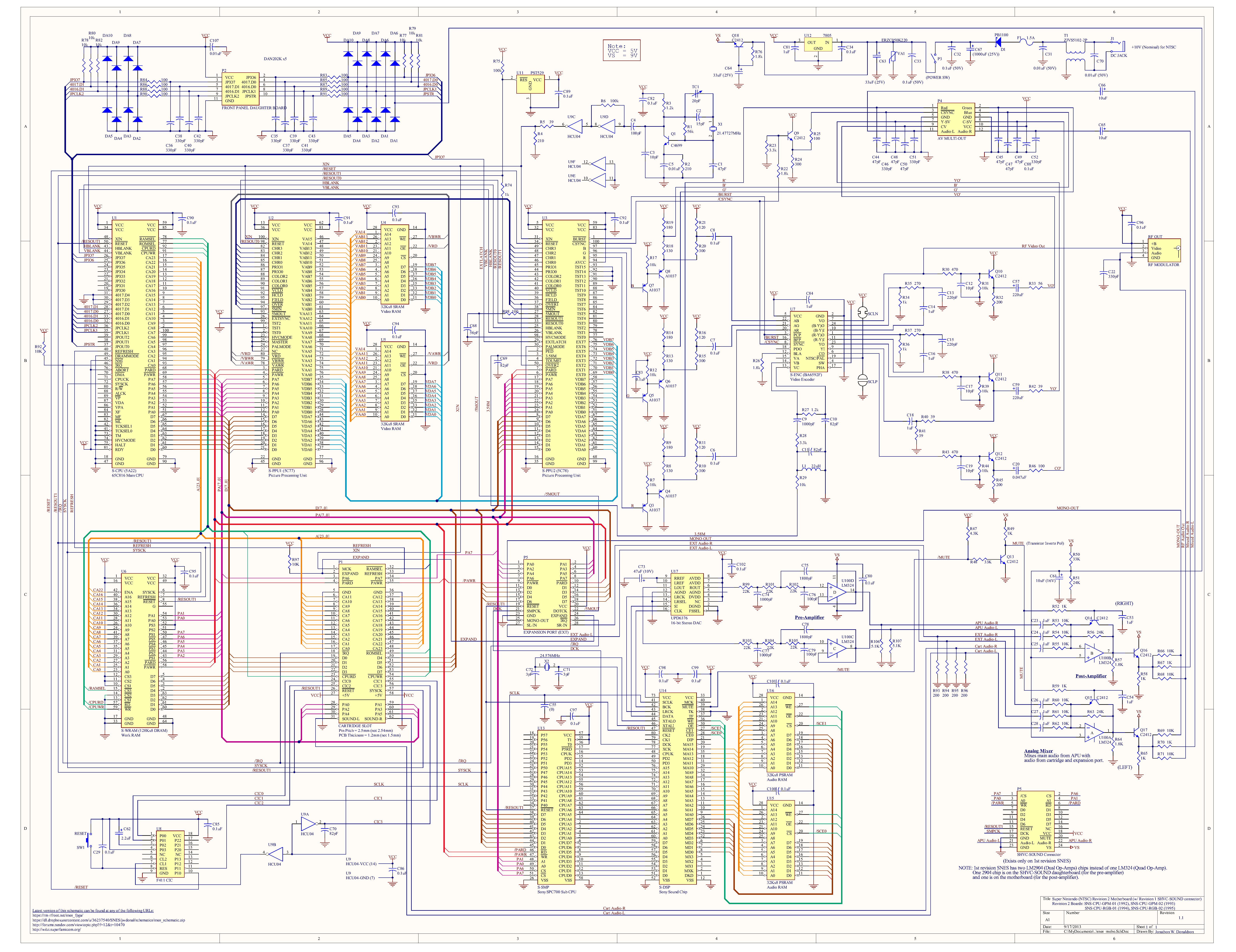
The schematics for the SNES and Genesis definitely show filters.
SNES (see B5)
There were two identical filters on R-Y and B-Y, before modulation, as well as what looks like a luma trap filter.
Genesis (right side)
There was a bandpass filter on the modulated chroma and a luma trap filter.
On some systems I barely notice a difference when eliminating the filters, but on others it is quite visible. There is a lot more chroma contaminating the luma, but if the chroma phase flips 180 degrees each frame it isn’t very noticeable outside of a bit of flickering. On systems like Genesis, though, it is very obvious on high contrast chroma transitions. Maybe less so with comb filtering.
The luma trap also contributes to the Genesis’ look. Especially on the early models, it rolls off the luma pretty early and blurs the output quite a bit. Someone modded a Genesis to “fix” the luma trap.
How effective the chroma filters on the SNES and Genesis were is, I think, an open question. I’ve tried to simulate them and they have less attenuation than I would expect. I asked an electrical engineer I know for help, so maybe we’ll see.
Interestingly, one system I can’t find any filtering on is the N64. There weren’t discrete filters on the circuit board (the chip no longer supported looping the signals back in) and I couldn’t find any mention of filtering in the ENC-NUS datasheet (you can find it here, previously posted by @PlainOldPants). It might have internal filters; I have no idea.
2 Likes
What about for Snes9x emulator? Turn off the NTSC filter?
For SNES, turn off the NTSC filter, and use p68k-fast-mp-snes.
1 Like
@Beans the question is how much the output filters on things like the SNES and Genesis affect the output. But thank you for sharing the info. It’s an important consideration. The unfiltered, square output of the NES certainly affects how it looks. For one, using square waves effectively shifts the perceptual phase (depending on how it’s detected) and square waves are also more susceptible to interference. For a sine wave, you need to distort the frequency of the sine, for a square, distorting any of the harmonics within band is enough to cause distortion.
The N64 has a nice output. I would be surprised if it’s not filtered.


It actually crazier than what I’ve posted it and Idk why.