Sony Megatron Colour Video Monitor

Hi @zedex some great questions. So with your first question it’s not possible to have arbitrary TVLs with pixel perfect masks. You can of course stretch and squish the image behind the mask to effectively get this but this probably won’t be aspect correct and you have to have a larger TVL to start with. The reason for this is that the mask is a fixed number of pixels - whatever that mask is. So with a typical 4 pixel aperture grille mask in order to calculate the max TVL your display can provide you need to divide the horizontal resolution by the mask size ie for a 4K display 2160/4=540TVL (max ie 16:9).

As for 2 you need some way to do that provided by the OS i.e lobby Microsoft or Apple or whoever makes the OS. Also probably the gfx card manufacturers. There’s probably some security risks with anything like this.

Lol yes will do but I warn you my drawing capability is child like.

1 Like

Hi @MajorPainTheCactus,

Congrats on the new TV! Pretty exciting specs it has!

I noticed your comment about updating all your presets because of the new tv. Will be great to see what comes out of that, it can only get better!

Regarding our earlier discussion on the vertical brightness distribution of a CRT scanline, i.e. the Gaussian profile discussed here, I thought to do a little testing to see how the scanlines in the pictures from your real Sony PVM 2730QM in the very first post of the thread (Randi - Secret of Mana SNES) match up vertically to the idealized gaussian profile.

As a starting point on a 4K TV we have 9 discrete steps for the vertical scanline modelling (2160p / 240p = 9 as scaling factor) . Since the vertical scanline profile is symmetrical from the midpoint to the top and from the scanline midpoint to the bottom, we need 5 discrete steps to start at the midpoint and move 4 steps up or down.

Given the 5 discrete steps in modelling the upper part of a scanline on 4K from brightest midpoint to the “black” in between the scanlines, what I did was I cut out a bit between the eyes from your CRT photograph, cutted it a bit further to the red, green and blue phosphor, then took the upper half of the pixel/scanline and rescaled it with paint package using supersampling to 5 pixel height. Then I measured the “V” with the HSV color system as the measure of brightness for the 5 steps and put it in an excel graph to compare it with the Gaussian Profile from that Chapter 5.

Like this:

to

cutout real 2730QM 1

to

cutout real 2730QM 2

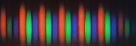
and then the middle of the top half for each primary color, i.e. approximately the yellow stripe in below image:

cutout real 2730QM 2 - middle cutout highlight

and scale that to a height of 5 pixels - using super sampling algorithm best quality from paint package - for getting the top half of the scanline brightness distribution (example below is inflated for visability).

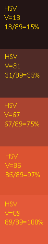
I took the very middle single vertical line for the top half, because we are only interested in the vertical profile. Then use the color checker in the paint program, take note of the “V” value from the HSV color system, make them relative to the midpoint of the scanline being the brightest at 100%. Example for phospor red:

cutout real 2730QM Red with annotation

Then plot the values symmetrically in an excel chart, which gives us the vertical scanline brightness distribution for your Sony PVM 2730QM:

Now super-impose the Gaussian Profile from the earlier discussed chapter 5.1 Generating the Pixel:

And somewhat surprisingly this gives the measured values a very near match to the idealized gaussian profile.

Now I hear you thinking, then what about my Megatron? :smiley:

So I did the exact same exercise for the equivalent Megatron picture from your first post (Randi - Secret of Mana SNES, cutout between the eyes from the Megatron simulation, etc, like above) and put them against the Real CRT measurements for Red, Green and Blue:

Red:

Green:

Blue:

I don’t know what exact preset/settings you used for that 2730QM Megatron shot, as you’ve been changing the presets and some shader code over time, but it seems, especially looking at the blue phospor vertical scanline brightness distribution that the simulation is actually very close to the idealized gaussian profile from the real CRT.

The red from this particular preset could use some tweaking, but the overal conclusion looks to be that the shader is quite able to match the vertical brightness distribution from the real CRT, and for that matter the idealized Gaussian profile from Chapter 5.1! :heart_eyes:

5 Likes

Really great work @rafan!

So on one level we can say just make the red and green mirror the blue settings!

On another level though I’m amazed that matches so closely to the point I’m a bit skeptical as there’s so many factors here. As in when I look at my CRT one area can look quite different to another area just with the naked eye - the beams do all sorts of widths and angles all over the screen and my phone is effectively flattening that all out from one particular area. Then we may not be dealing with perfect colours because of the camera, original colour etc swinging that HSV calculation not to mention all the processing the camera is doing with tonemapping and converting that into jpegs etc. I also took the picture and then screen grabbed a zoomed in version of that so double processing it. Then what is the super sampling algorithm doing and all that processing. It would just seem a bit too good to be true surely?

Then again you’ve shown your workings and crunched the data and mapped it to the diagram so who am I to argue with that - I’m just amazed its come out that close - nearly perfectly. I’m also just as amazed that I got the shape that accurate just by eyeballing it especially as I was mainly looking at the lengths of the phosphors and not in the shape of the falloff particularly.

I suppose at the end of the day though all these things I’ve said haven’t dramatically altered the look as in you are still looking at recognizable images of phosphors and so maybe it will keep all the luminance information pretty much intact. Quite amazing results though and great thinking.

4 Likes

Thinking about this some more with the Megatron because we know the values and calculations we can get the actual curve out of it for the settings and see exactly how it matches that curve. Whether that makes it match the optical output of the LCD to the CRT though is very much up in the air.

2 Likes

Ok so with the S95B one of the first things I did was to take pictures of the white, red, blue and green screens of the test suite. With a particular interest in the mask accurate Vs colour accurate modes. I took these pictures of my TV in ‘entertain’ mode as game mode absolutely destroys the image (needless to say I will get back to game mode in a later post).

So here are the money shots of colour accurate first (all using rec. 2020):

1 Like

And now of mask accurate:

3 Likes

Apart from mask accurate not looking right because it’s broken out the component colours of the HDR colour it’s also got the original issues of the colour accurate colours as in that rec. 709 green is a slightly red (yellowey) green in rec. 2020 and the same goes for the other primaries. What I will say is that although the phone shows the other sub pixels lit up in the colour accurate mode with the naked eye they look completely green and completely blue and completely red. It’s only the mask accurate ones that don’t (with the naked eye).

All in all I can’t understand how mask accurate currently looks right for anybody - this is odd. I do think there is a bug in mask accurate currently though as in I was thinking it would be pure green and it’s not it’s yellowey green. I need to look into this!

2 Likes

Are RGB and BGR mask layouts working as expected? Is the “strange” non IPS/VA like subpixel layout that we saw in the initial reviews of the QD-OLED panel an issue at all?

Is it safe to purchase a QD-OLED TV if you want accurate CRT Mask emulation (which seemed to be one of the initial targets of the Sony Megatron Color Video Monitor)?

I find it strange that no one else has asked any of these questions yet.

1 Like

This is a QD-OLED so it’s a RGB mask layout the same as my LCD. I suppose I should qualify that in my shader parameters shouldn’t I! In terms of the triangle sub pixel arrangement and aperture grille I’d say it’s absolutely fine. For slot masks up close you can see a little bobble but as you draw away your eyes snap them straight. Basically at a foot away from this six foot screen you can see the bobble but at a foot and a half you see a straight normal slot mask. As for dot masks I haven’t tested them yet - these will be the interesting ones!

2 Likes

With regards to the CRT mask accurate this isn’t really an issue with the shader per se it’s to do with rec. 2020 and using HDR which effects all shaders in HDR. Admittedly HDR is a key part of the Megatron so it’s fair argument in one respect.

So does HDR/rec. 2020 break the masks? I’d argue it doesn’t in practical terms but technically you can argue it does. Certainly in person with the naked eye with your nose pressed up against the screen you can’t see the green subpixels being on in the red screen - the red screen is red and made up of faked red phosphors as far as you’re concerned.

This kind of makes sense as the red rec. 2020 sub pixels are trying to make the same colour as the red rec.709 pixels or indeed the red rec.601 phosphors which were both slightly greener - but you wouldn’t at the time say they were greeney red you would just say they were red.

The question Im trying to figure out is when I output pure red from my shader is the TV turning on those green sub pixels as its doing in mask accurate mode. Is this windows, the gpu driver or the TV converting that red into rec. 2020’s equivalent red. This may show us a bug somewhere which would be important to fix.

1 Like

Congrats on the tv purchase.

Can you take some slot mask pics for us?

2 Likes

Rest assured I have got them - I’ll share them soon!

2 Likes

Honestly thinking of selling my C1 for this. I never remedied the sound lag issue that plagues my C1 and LG offered little to no support to fix my issue. If CRT mask emulation is superior to standard OLED’s I’m sold.

1 Like

Here’s some pics of slot mask on Sega Virtua Racing (a typical look of Virtua arcade game cabinets) on the S95B. When you zoom right in you can see the ‘bobble’ on the horizontal wires but when you zoom out it vanishes which is how it works in person.

Do zoom in on the third close up picture to see both the slot mask and pixels making up the phosphors in detail and in HDR. Apart from the bobble even the slightly larger gap between the blue and red pixels (vertical wires) work well as they seem to match the height of the horizontal wires

7 Likes

The subpixels do look a bit strange in the extreme close up, but perhaps the glow disguises that at greater than nose-to-screen distances. I think what we need are some side-by-side comparisons! Time to see if it passes the Pepsi challenge.

2 Likes

Yeah there’s definitely no getting around the fact it’s going to have slightly odd spacing but you need a camera set to 100 and below ISO to tell I’d say - it’s just too bright to see the individual sub pixels that well but I need to setup my PC in the front room again and find time now that Ive digested the photos a bit and definitely we need to do a pepsi challenge!!!

Just to add one thing I noticed is the larger spacing between the blue and red phosphors in the images but maybe you could argue that’s more like an actual CRT with it’s slightly wider wires between the triads? 🤷

1 Like

Well I was thinking theoretically it should be possible to emulate an electron beam’s width with enough resolution.

Not sure if you were aware but there is this thread on Shmup Forums which details how you can modify the TVL of a CRT to whatever you want by modifying the spot size(electron beam width) There are some very in-depth explanations here(some from Texas Instruments) which might be of use to you https://shmups.system11.org/viewtopic.php?f=6&t=67124&sid=d36961dab98500a962e7bc97015f63c0

Seeing as both CRT and Modern Displays are Raster-type displays, given enough resolution it should therefore be able to recreate the same effect. Although I’m unsure of the math/method involved to do it and how much resolution you would need to do it. I know for a fact though that CRTs were not pixel-perfect by design, at least the ones that used masks. What I’m thinking here is more “line-perfect” rather than pixel perfect.

2160/4=540tvl Pretty sure it’s 3840/4 = 960TVL Or for 4:3 2880/4 = 720TVL Since TVL is the Horizontal Resolution not the Vertical one

For 2: Why would you possibly need that provided by the OS or the Graphics Card? A 3rd party open source software solution would work.

2 Likes

I’ll come back to 1).

As to 2) maybe I’m misunderstanding what you’re after? As far as I can tell youre after a full screen shader that runs over the entire Windows desktop at all times. Have I got that right? If not then why wouldnt ReShade work for you?

So assuming you want the former you might be able to do something like via the likes of a virtual monitor AKA Parsec but obviously you’d need shader support in the virtual monitor driver rather like I was saying for the Nvidia or AMD drivers.

Possibly you might be able to capture the desktop like the snipping tool and display a full screen app over the top but then how do you feed all the mouse keyboard etc events to the Windows subsystem and on top of that good luck with full screen apps. I can’t see how that would realistically work.

1 Like

So to 1) changing the beam spot size isn’t increasing the TVL at all, although I can see it having the effect of doing that. Your TVL is basically fixed to the number of phosphor triads you have and that can’t change. Changing the spot size effectively makes the beam more reactive to the current phosphor and underlying image giving a sharper image.

With shaders you can do this way more accurately as can be seen especially in Reshade where you can have effective TVLs of 2160p if the underlying content is 3840 horizontal resolution.

Basically we change the spot size already and you can change that with the horizontal (and vertical) attack in the Megatron.

TVL is the count of vertical lines across the screen to the height of the screen across i.e a square. That’s why we just use the vertical resolution.

1 Like