Sony Megatron Colour Video Monitor

Thanks for the video I’ll take a watch as for your questions I’d have to get my head back into the shader and those matrices and transfer functions again. In the mean time here’s the Kronos Groups low down on them chapter 13 is all the transfer functions and 14 are all the colour primaries conversions:

https://www.google.com/url?q=https://registry.khronos.org/DataFormat/specs/1.2/dataformat.1.2.pdf&sa=U&ved=2ahUKEwilsMeM6Jf6AhVtQEEAHZ2tCBsQFnoECAYQAg&usg=AOvVaw2B53QFDWWO_j2LvPFej4Nv

I vaguely remember the transfer functions working on the ‘intermediate’ XYZ colour space although I could be completely wrong and they work on the input/output RGB spaces - it’s definitely one of the two!

3 Likes

Thanks for the link to the Khronos document.

So the transfer functions work on the input and output RGB spaces.

As far as I can see it’s not very explicit about what gamma is applied on the input RGB (to make it the required linear input) and what gamma is applied on the output. On the Bruce Lindbloom site it mentions in both the RGB to XYZ section and XYZ to RGB section that “the operation depends on the companding function associated with the RGB color system.”

Taken literally, in the case of converting the 709 space/primaries to DCI-P3 space/primaries one would implicitly create a gamma correction, as input linearization is done with rec.709 gamma ~2.2, but output is done with DCI-P3 gamma of 2.6.

That seems a bit strange… If I look at guest.r method, he only uses the output space gamma value for both input and output (so 2.6 in case of DCI). Seems to make more sense, since you’re not implictly doing gamma correction, while remaining the transformation of the color primaries.

Also what I’m reading in the Bruce Lindbloom site is that the input and output space need to have the same whitepoint defined or otherwise the difference needs to be accounted for via chromatic adaptation (read: complicating things further?). I’m not sure how your whitepoint adaption in your shader ties in with the color space transform, but possibly it’s something to keep in mind?

Unfortunately most of the above doesn’t seem to help much with the shader issues we discussed, I think…

3 Likes

So you need to convert into linear space to convert your colour primaries and then back out into the accompanying gamma space.

I might be able to look at this tomorrow and just see if I can spot on anything. Hopefully shouldn’t be too hard to figure out what’s wrong here.

3 Likes

@rafan so found the issue! My gut instinct was right - it was a precision issue and a complete school boy error by having my SDR linear space buffer in low precision. Upped it to float 16 and bang fixed the weird issues.

So one thing you’ll notice now is that those bars in SDR are still very dark however they aren’t clipped now, they just contain very dark values. If you remove the sRGB gamma clip which is part of the sRGB standard and just replace it with a direct pow(X, 2.4) they pop back up but I’m keeping with the standard. I can elaborate on this if you’d like to try yourself.

HDR is unaffected by this as it uses the PQ transfer function. Although it would have been affected by the precision bug.

All in all this fix should be a large quality improvement so thanks rafan!

The pull request is Sony Megatron 3.5.

LCD Photos: OnePlus 8 Pro Camera: Pro Mode, ISO 400, WB 6500K, Aperture Speed 1/60, Auto Focus, 48MPixel JPEG.

5 Likes

Quality improvements welcome! Thanks @rafan & @MajorPainTheCactus! Gorgeous screenshot by the way!

1 Like

@MajorPainTheCactus Just thought I’d let you know it appears the BGR version of the 8K RYCBX mask just repeats the RGB version. It ought to output BCYRX, but ends up outputting RYCBX anyway. Fixing it is as simple as editing line 378 from

kRYCBX, kRMCGX, kRYCBX

into

kRYCBX, kRMCGX, kBCYRX

2 Likes

Good catch! Thanks - I’m sure there are more of these lurking around what with all the tables!

1 Like

That’s awesome @MajorPainTheCactus, gamma issues are fixed now! Thanks! :heart_eyes:

One issue remaining is the subpixel output when setting colour space to DCI-P3

"SDR: Display's Colour Space: r709 | sRGB | DCI-P3" to DCI-P3.

Then I’m getting a messed up subpixel output like below. It’s most visible when setting TVL to 1000.

whereas with Color Space set to 709 or sRGB I do get a clean subpixel output:

Could you test this by loading “crt-sony-megatron-sony-pvm-2730-sdr.slangp” preset, then -only- change “SDR: Display’s Colour Space” to DCI-P3 (setting 2.00), TVL to 1000 and check the subpixel output on a white screen?

Edit: I mentioned before that I’m testing this on 1440p monitor with native RGB subpixels.

Edit 2: a picture of the native monitor RGB subpixel layout

Output3_native_no_shader

2 Likes

Some additional test results to previous post, but now for HDR mode.

When using RA in HDR mode and loading 2730-HDR preset, whatever setting I change, the mask output is incorrect, similar to SDR mode in DCI-P3, e.g. for Aperture Grille| 4K | 1000TVL:

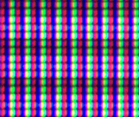
Since HDR mode is ALWAYS doing the color gamut transformations (either 709 to 2020 space or “extended/vivid” to 2020 space) it seems that this colour gamut mapping is a source of messing up the mask output.

I think replacing the color transform matrix in the HDR shader with a unity matrix (i.e. it would pass native colors without doing any transform) could be good test case, to see whether then the mask output returns correct. That would confirm the transform between different gamuts is causing an issue.

Edit: So I’ve just tried it, replacing the transform matrix for 709 and expanded709 in include/hdr10.h

Note the matrices seem to already be the product of RGBtoXYZ and back out XYZtoRGB, i.e. 709(RGB)toXYZ * XYZto2020(RGB), both for 709_to_2020 and also this seems the case for the Expanded709_to_2020 matrix

/*
const mat3 k709_to_2020 = mat3 (
   0.6274040f, 0.3292820f, 0.0433136f,
   0.0690970f, 0.9195400f, 0.0113612f,
   0.0163916f, 0.0880132f, 0.8955950f);

/* START Converted from (Copyright (c) Microsoft Corporation - Licensed under the MIT License.)  https://github.com/microsoft/Xbox-ATG-Samples/tree/master/Kits/ATGTK/HDR */
/*
const mat3 kExpanded709_to_2020 = mat3 (
    0.6274040f,  0.3292820f, 0.0433136f,
    0.0457456f,  0.941777f,  0.0124772f,
   -0.00121055f, 0.0176041f, 0.983607f);
*/

Replace by a “unity” matrix, such that there’s no transform and native colors get passed on:

const mat3 k709_to_2020 = mat3 (
 1.0f, 0.0f, 0.0f,
 0.0f, 1.0f, 0.0f,
 0.0f, 0.0f, 1.0f);
 
const mat3 kExpanded709_to_2020 = mat3 (
 1.0f, 0.0f, 0.0f,
 0.0f, 1.0f, 0.0f,
 0.0f, 0.0f, 1.0f);

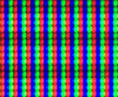
And indeed the mask issue is solved, the shader subpixel output is clean RGB (RBG):

Now the million dollar question, can you think of any reason why color gamut mapping (e.g. 709 to DCI-P3 (in SDR mode) or 709 to 2020 (in HDR mode) in the shader is causing the mask output to get “messed up”?

It would be really nice if this could be resolved or at least understood why it is causing this result.

2 Likes

Hi rafan great stuff so we’re making progress. So aperture grille 4K 1000TVL should be selecting a Magenta Green mask but what you’re seeing is yellow and cyan in there too? This is odd. Maybe I haven’t taken into account the relative recent conversion into XYZ but then I’d expect that to be influencing every mask. I’ll take a look my end.

1 Like

Hi @rafan, so although my camera isn’t good enough to capture the sub pixels of the high density 1000TVL mask on my 27" 4K monitor I am able to take a screen grab of the shaders output and it looks like this:

which looks correct as in its a pure magenta green mask which is what the 4K 1000TVL options would select as a mask.

Also the maths all works out I think. The main shader (last pass) deals with rec. 709 colour primaries (see line 158 in colour_grade.h) not XYZ colour space and so all of the last colour gamut transforms should be from rec. 709 space (sRGB uses the same colour primaries as rec.709 it just uses a different gamma curve).

If you put those matrices to identity then you’ll still be in rec .709 space and so (I’d guess) your monitor is in that space and not DCI-P3 or rec.2020 and hence why it looks correct using identity.

So I say all that with the massive caveat that I’ve understood you correctly - I can misread things.

2 Likes

Just released Sony Megatron 3.6 which fixes the 800TVL BGR aperture grille mask bug that @GPDP1 pointed out above. Thanks GPDP1 greatly appreciated! Also tweaked the shader parameters to be more intuitive with respect to gamma in/out and HDR/SDR (as gamma out isn’t a thing for HDR).

Also recalibrated the Sammy Atomiswave presets to try and get closer to the arcade screen with the new high precision gamma:

Much better reduction in detail that the arcade screen ‘suffers’ from - you can see the arcade version (and my previous attempt) right at the top of this thread. Its certainly better I think.

3 Likes

Hi, thanks again for looking into this.

I’m having the issue not only with 1000TVL, it’s with all the TVLs.

When the shader is in sRGB mask output is fine. If then the only change I do is put the shader setting colour space to DCI-P3 then the mask output goes awray.

Example: I load up your 2730-SDR preset and change TVL to 300, then this is my output (iphone protograph so not the best, but I verified with magnifying glass). It’s great!

output1new

Now I F1 and ONLY change colour space to DCI-P3 in the shader. It’s really the ONLY change I do, then output becomes this:

output2new

It’s quite bad as you can see, next to the red other subpixels light up, and next to green the same.

If I then F1 again and change colour space in the shader back to sRGB then output is good again (like the first picture).

It looks like mapping a color space into another in the shader affects the mask. As long as NO color space is set, everything looks OK.

Can you do the following on your end: load 2730-SDR preset on your end, change TVL to 300. Make a picture, then go into shader settings and change colour space to DCI-P3, make a picture again. You must see a difference, or not?

2 Likes

I’ll try that specifically but I’ll be honest I’m not seeing that much of a change flipping between them so far.

One thing I would say though is that you should be setting your monitor to the corresponding colour space too - what happens if you select DCI-P3 in your monitor settings and flip between the two?

Its kind of a kin to selecting a HDR shader when your monitor is in SDR mode. It’ll look terrible.

I’m going to sleep right now but I’ll try and get some time tomorrow to do these tests for you.

2 Likes

Thanks, that’s appreciated. Possibly you could test with the 240p test suite “White & RGB Screen” test. If you press “W” on the keyboard you can cycle between White, Black, Red, Green, Blue screens.

I can clearly see unwanted subpixels light up on the Green subscreen when switching to DCI-P3 color in the shader.

Just out of interest, are you testing on a wide gamut monitor or sRGB monitor?

2 Likes

Hi @MajorPainTheCactus

I’ve got an additional more objective test related to the colour space settings of which the result seem strange: the luminousity of a pure white screen changes when cycling between the 3 colour spaces: the white screen shader output gets brighter with each change from colour space 709 to sRGB to DCI-P3

Would be great if you could do the following test:

First make the RA menu transparent such that when changing the shader colour space setting you see the result while in the menu, it makes the luminousity changes easier to spot when cycling through the colour spaces.

Go to Main Menu -> Settings -> User Interface -> Appearance -> Framebuffer Opacity and set this to a value of 0.00 (menu becomes fully transparent such that you can see the shader output when in the menu)

Start the SNES 240p test suite and go into test patterns “White & RGB Screens”, stay on the white screen.

Load the megatron 2730-sdr preset, go into the shader menu and cycle between the three colour spaces:

SDR: Display's Colour Space: r709 | sRGB | DCI-P3

You’ll see the luminousity/brightness of the 240p white screen increase with each step: r709 darkest, sRGB brighter, DCI-P3 brightest

Now since the white screen has no saturation I assume the luminousity of a full white screen should definitely not change when changing the colour space.

The only thing I could think of influencing the result is that the 709 and DCI-P3 matrix would be created with different white points, but as far as I can see they are both created with D65 white.

To be absolutely sure, Ive repeated above test on a completely different monitor (1080p sRGB), and the exact same happens, the luminousity of the 240p full white screen test increases with changing the shaders colour space settings…

Any idea what could be an explanantion or cause for this?

3 Likes

Yes so this is expected and is kind of a problem with the limited interface we have for the shader params. Each of the colour spaces, rec.601, rec 709, sRGB and rec.2020 isn’t just colour primaries it’s also a transfer function too and from optical and electrical spectrums. With rec.709 and below this a gamma curve, with rec.2020 this is a PQ function.

When you cycle through the colour systems youre also changing the gamma curve which is why we see the change in luminosity. Rec.709 is ^2.22, sRGB is ^2.4 and DCI-P3 is ^2.6. Because I can’t change values in the menu based on other values in the menu behind the scenes I add 0.2 to gamma out for dci-p3 and minus 0.18 for rec.709 onto the menu value of 2.4. Ideally we’d just change the menu values for gamma when we change colour space.

However I do see your point in that on a pure white screen we shouldn’t see this as everything would be at 1 but is everything at 1? As these masks mask out channels to red, blue and green and then we have the drop off in intensity from the center of the scan line to the outer part. I’d guess at this point you will see a change in luminosity for certain.

So based on that there maybe a good argument for changing into the output colour/gamma space before we do the main shader. I’ll try that and see where it gets us in terms of white stability.

Thanks for these tests and thoughts it’s great appreciated. I will try this out hopefully today.

3 Likes

Just thinking about this some more and although I’ll try this out (moving the gamma before the main shader) I’m not sure it’s correct. As in before the main shader we’re effectively in CRT space i.e rec.601 (I should probably change it to this from rec.709 as it currently is).

However when we come to DCI-P3 and rec.2020 these colour spaces didn’t exist back then and so are part of the conversion to your actual modern monitor from CRT. These should come after the main shader with probably the artifacts you’re seeing.

Ok you could change them before and get more luminosity stability but is that actually correct as in what a CRT scanline drop off would do with a different transfer function. Not sure.

2 Likes

I see your point.

I’m still not sure whether the artifacts I’m seeing regarding the mask output is to do with the curves alone. There’s an itch with this gamut mapping, that I’d like to at least understand a bit better.

I created a fictitious “Limited 709” space that is using desaturated 709 primaries for red and green. Mapping this one into 709 is the equivalent of the 709 to wide gamut mapping (DCI-P3/2020) but has the benefit that we keep 709 as output space, such that we can possibly rule out issues related to wide gamut modes.

The interesting finding is that the mask output gets messed up when color mapping of “limited 709 space” to regular 709 space is done, i.e. when a color gamut transform is active, while with regular 709 the mask output is a clean RBG.

Below is the patched gamma-correct.h. It’s a quick hack, but it gives the idea. Hopefully this is useful in tracking down why the mask output is so different (wrong?) when a color gamut transform is active.

Note that when you replace gamma-correct.h with this version, then the colour space parameter 709 and sRGB actually switches between “regular 709” space and “limited 709” in 709 space. Also the transform for regular 709 is done pro forma, as it’s a transform from 709toXYZ and XYZ to 709.

For me when using “limited 709” I can see the mask output being messe up when doing macro zoom on the subpixel output in the white screen of the 240p test suite. Contrary when setting regular 709 the mask output is clean RBG.

// SDR Colour output spaces

const mat3 k709_to_XYZ = mat3(
   0.412391f, 0.357584f, 0.180481f,
   0.212639f, 0.715169f, 0.072192f,
   0.019331f, 0.119195f, 0.950532f);
   
const mat3 kXYZ_to_DCIP3 = mat3 (
2.4934969119f, -0.9313836179f, -0.4027107845f,
-0.8294889696f,  1.7626640603f,  0.0236246858f,
0.0358458302f, -0.0761723893f,  0.9568845240f);

// "709limited" - fictitious 709 space with less saturated red and green primaries
// Wx=0.3127, Wy=0.329 -- D65 white
// Rx=0.50, Ry=0.33 -- less red saturation than 709/sRGB primaries
// Gx=0.30, Gy=0.50 -- less green saturation than 709/sRGB primaries
// Bx=0.15, By=0.06 -- Blue same as 709/sRGB

const mat3 k709limited_to_XYZ = mat3(
0.4182745739f,	0.4034733473f,	0.1287080058f,
0.2760612188f,	0.6724555789f,	0.0514832023f,
0.1422133551f,	0.2689822316f,	0.6778621641f);

// XYZ to 709
const mat3 kXYZ_to_k709 = mat3 (
   3.2409699419f,	-1.5373831776f,	-0.4986107603,
  -0.9692436363f,	 1.8759675015f,	 0.0415550574,
   0.0556300797f,	-0.2039769589f,	 1.0569715142);


float LinearTosRGB_1(const float channel)
{
	return (channel > 0.0031308f) ? (1.055f * pow(channel, 1.0f / HCRT_GAMMA_OUT)) - 0.055f : channel * 12.92f; 
}

vec3 LinearTosRGB(const vec3 colour)
{
	return vec3(LinearTosRGB_1(colour.r), LinearTosRGB_1(colour.g), LinearTosRGB_1(colour.b));
}

float LinearTo709_1(const float channel)
{
	return (channel >= 0.018f) ? pow(channel * 1.099f, 1.0f / (HCRT_GAMMA_OUT - 0.18f)) - 0.099f : channel * 4.5f;  // Gamma: 2.4 - 0.18 = 2.22
}

vec3 LinearTo709(const vec3 colour)
{
	return vec3(LinearTo709_1(colour.r), LinearTo709_1(colour.g), LinearTo709_1(colour.b));
}

vec3 LinearToDCIP3(const vec3 colour)
{
	return clamp(pow(colour, vec3(1.0f / (HCRT_GAMMA_OUT + 0.2f))), 0.0f, 1.0f);   // Gamma: 2.4 + 0.2 = 2.6
}

void GammaCorrect(const vec3 scanline_colour, inout vec3 gamma_out)
{
   if(HCRT_HDR < 1.0f)
   {
  if(HCRT_OUTPUT_COLOUR_SPACE == 0.0f)
  {
     const vec3 Rec709_colour = (scanline_colour * k709_to_XYZ) * kXYZ_to_k709; 
     gamma_out = LinearTo709(Rec709_colour);
  }
  else if(HCRT_OUTPUT_COLOUR_SPACE == 1.0f)
  {
     const vec3 Rec709_colour = (scanline_colour * k709limited_to_XYZ) * kXYZ_to_k709; 
     gamma_out = LinearTo709(Rec709_colour);
  }
  else
  {
     const vec3 Rec709_colour = (scanline_colour * k709limited_to_XYZ) * kXYZ_to_k709; 
     gamma_out = LinearToDCIP3(Rec709_colour);
  }
   }
   else
   {
  gamma_out = Hdr10(scanline_colour, HCRT_PAPER_WHITE_NITS, HCRT_EXPAND_GAMUT);
   }
}

Output when “Limited 709” is selected:

Output with regular 709:

2 Likes

So let’s separate out two things we’ve been talking about here:

  1. there’s an issue you’re seeing with the mask in DCI-P3
  2. there’s a change in luminosity as you change between SDR colour spaces

I think we can tick off 2) or at least is less of a priority as it makes sense. I’m much more interested in 1) for the time being as it seems less understood.

With regards to 1) I’ll try on my monitor the test we were talking about with 300TVL and pure red screen as I think you said that was the more obvious repro case.

Does that sound like a good idea?

My hunch at the moment is that this is some kind of post processing that kicks in by the monitor in wide colour gamut modes as we’re seeing similar things with other users when they use HDR and yet HDR on mine is fine.

Let me do the tests and see if I can repro the issue you’re seeing.

In the meantime itd be good to see if you can see the issues you’re seeing in a screen grab i.e with the snipping tool as this will separate out what is monitor and what is shader ie if we see the same errors in the screen grab we know the problem is in the shader and if not then the problem is at some point down stream ie gfx card, driver, port, cable or monitor.

2 Likes