Sony Megatron Colour Video Monitor

Hi @MajorPainTheCactus

Thanks for your work on the shader. Have been playing around with it and noticed that in the 240p test suite on SNES in the color bars and gray ramp tests that the darkest colors get cropped (they are black). Happens both with HDR in RA OFF or ON.

Any idea why this is happening?

Tested with latest RA from the buildbot and your latest shader updates. Everything in vulkan slang.

2 Likes

Hi @rafan, first of all thanks for flagging this. So what values are you expecting the darkest colours to be? I’m not up on the specifics of the test suite but I would’ve expected the values to go from 255 to 0 at the stepping rate the SNES could handle and so result in black at the farthest step.

Things you could try are setting all the brightness, contrast etc shader params down to 0. Also in SDR making sure your monitor matches the output colour gamut usually rec .709 or sRGB.

If possible some photos of what you would expect vs some of what you actually got. I’ll take a look my end but I’m away ATM so it maybe a while before I get back.

2 Likes

Oh, sorry! Busy month. Sure!

1 Like

Hi @MajorPainTheCactus, thanks for the answer. I tried your suggestions but the darkest value remains cropped.

I’ll explain a bit what I’ve tested and what I expected versus what I’m getting.

I’ve been testing everything in SDR mode with your SDR shaders.

The Gray Ramp test in SNES 240p test suite has a number of bars, of which the most left is black (RGB 0,0,0) and the bar second to left starts with darkest grey (RGB 8,8,8) and then increments the bars at about RGB steps of 8,8,8 (so third bar is 16,16,16, etc).

On a CRT with RGB/SCART connection that has properly set brightness and contrast, ALL the dark bars are visible, starting with the second to left bar (RGB 8,8,8). This is assuming watching in a dimly lit room.

In below picture I highlighted the bar that is cropped to black in your shader, it’s the second bar with RGB value 8,8,8.

240pSuite-SNES-grayramp-with-RGB-value

I’ve noticed that in some cases your shader is cropping more dark color bars, so then even the third and fourth bars (16,16,16 and 24,24,24) are cropped to black. Note that they’re really cropped (clamped?) to RGB 0,0,0.

If and when you have some time you could do the following:

  • run the SNES 240p Gray Ramp test WITHOUT shader, then make sure you calibrate your monitor such that you can see all dark bars including the RGB 8,8,8 one.

  • Then apply one of your shader presets an you’ll see the darkest bars getting cropped.

You can bind keys to “previous shader” and “next shader” (I think default are “N” and “M”). If you have an empty shader next to your preset, you can switch back and forth between the non-shaded and shaded output. Very helpful for seeing the difference, what’s being different and whether the shader output is gamma neutral.

In this regard I noticed that changing between “SDR: Display Color Space: 709 | SRGB | DCI-P3” makes a large difference in the amount of dark bars cropped.

Looking at your code I see you’re applying different gamma values here, but note that changing gamma by approx 0.2 shouldn’t result in cropping the darkest bars to black (it could make them at best a bit darker, but not crop them to black).

Thanks again for the marvelous work on the shader, apart from this dark bar(s) cropping everything is great!

2 Likes

Brilliant @rafan thanks for the detailed description of what’s going wrong. I’ll take a look and see what’s happening.

My guess at this point if everything is at a neutral setting is that because this shader only lights up a fraction of the sub pixels it needs an extremely bright monitor to see these dark bars.

As in the few sub pixels it is lighting up in the dark bars are of the correct values as in 8 but because they are surrounded by a sea of actually black pixels we perceive these bars as being black.

I don’t know if you’ve taken a screen shot and eveyballed the values in a paint package to rule this theory out (they would be value 8 gamma corrected). I’ll try and do this as part of my investigation bear with me.

3 Likes

@rafan Something to try is to remove the mask. This can be done by selecting 1080p and 1000TVL in the shader params. This won’t turn off the scanlines though so only a narrow set of pixels in the vertical direction will be at ‘full brightness’ but might help with the perception of darkness.

2 Likes

Thanks for investigating.

I tried your below suggestion, but it doesn’t make a difference to the “8” bar, it remains black. Even though all other bars (the ones 16,16,16 to 255,255,255) get much brighter.

I noticed a few things upon further testing. Just as an example, after loading the atomiswave SDR preset: If I lower “gamma_in” to a level of 1.76 or lower, then the 8 bar “pops” in. Or if I leave gamma_in at 2.02 (the preset default) but lower “contrast” to something equal or lower than “-0.26” than the “8” bar also “pops” in.

However when doing this the rest of the image gets washed out, so it’s not a solution. I would imagine this big a gamma change is unwanted and the bar should be visible when gamma values are near defaults for CRTs and LCD (say at least inside the range of 2.0 to 2.4.) But maybe this finding provides a clue?

Further I’m not really sure how important it is that the “8” bar is really visible, since the rest of the gray ramp seems fine? And because maybe such low RGB values like the 8,8,8 bar were never really used by gfx artists in video games?

I can imagine in daylight/arcade setting one would never be able to distinguish the 8,8,8 from black, so probably artists would go with darkest values like 16,16,16 and up that would be distinguishable from real black (0,0,0) in daylight setting? But that’s just guessing…

.

2 Likes

@rafan so you’ve definitely found an issue but I’m not sure what it is that’s going wrong. My feeling is that’s it’s something to do with the gamma in value.

As an immediate work around just tweak the gamma in to be around 1.8 maybe a bit lower - what we’re looking for is that the first bar has a value of 1,1,1 ((8/255)^2.2)*255) and the second bar has a value of 5,5,5 ((16/255)^2.2)*255) . The colour system should probably be set to rec.709 for this as it skips the white temp which biases against the red channel.

When I change gamma in though I’m seeing some very strange behaviour (as in the center of the scanlines go to black whilst the outside of them are brighter) and I need to investigate this.

3 Likes

Yes this matches up with my findings - something is going on at the low end - in the very darks. My guess is that there’s some precision issue or something.

3 Likes

Hi @MajorPainTheCactus

Based on my testing below a gray ramp issue seems to be introduced with the March 14th 2022 release: commit 2237891

Hope this helps in pinning down the issue.

Did some random testing with previous releases and can report the following releases have no issues, gray ramp is fine from 8,8,8 to 255,255,255:

The following releases have issues:

I will update this post when I find others.

Edit: everything tested with shader parameters brightness, contrast, saturation (when available) and gamma (when available) at neutral

4 Likes

Fantastic work @rafan! Thank you very much for doing this - as I’m sure you’re aware it’s incredibly useful to know when this started happening.

3 Likes

Hi @MajorPainTheCactus

I would like to extend some of my testing with the shader, and noticed that on my 1440p monitor shader output white is different from my 1080p monitor (both are native close to D65). Looking up close I can see on the 1080p monitor the shader output is doing “RBG” subpixels cleanly. While on the 1440p monitor the shader output is not outputting subpixels cleanly, the best I can get (changing 1080p|4K|8K parameter and 300|600|800|1000TVL parameter) is something like RBRG.

Is that due to needing explicit 1440p support added to the shader, or something else?

FYI both monitors have a normal native RGB subpixel layout. So my second question is whether it’s normal for the 1080p monitor to have the order changed by the shader to RBG? (note changing RGB|BGR does not change this).

2 Likes

Hi rafan so the resolution is only there really to choose the appropriate mask for the desired target TVL. You can use what ever resolution you like it’s just going to choose a different mask based on that.

As for RBG thing that is odd what are you choosing for TVL, resolution and CRT type? There maybe a bug in the mask code for that particular mask.

2 Likes

I’m choosing 4K | APERTURE GRILL | 1000TVL.

Could you let me know what your preferred version is to test with? Is it the latest commit and then HDR mode or SDR? I will then try to make a photo of the results.

Edit: and what preset should I start with? crt-sony-megatron-sony-pvm-2730-sdr.slangp or crt-sony-megatron-sony-pvm-2730-hdr.slangp or another one?

2 Likes

Hi rafan sorry for the delayed response. The preset you should start with is definitely 2730 SDR or HDR. Possibly SDR is less ‘dangerous’ as in less things that can go wrong but that’s probably subjective. Always latest commit should be good (should be :rofl:).

I’ll take a look at that 4K mask and see if there is a bug with it.

2 Likes

Hi, thanks for answering. I’ve been doing some more testing with latest release in SDR mode and I’ve found something that I’m sure will help you tackle the issue.

The issue with the 4K mask that I mentioned is being caused by the colour grading that is present in your shader.

I’ve used the 2730 sdr preset as a base and changed a few settings, mostly making things neutral and adjusting gamma as we discussed. See my preset quoted at the end of this post.

Currently this is tested with the shader colour space set to dci-p3 output, since it is what my monitor sdr output comes closest to and it also having the best gray ramp

With this preset the 4K|1000TVL mask output looks like this, which is obviously not how we want it:
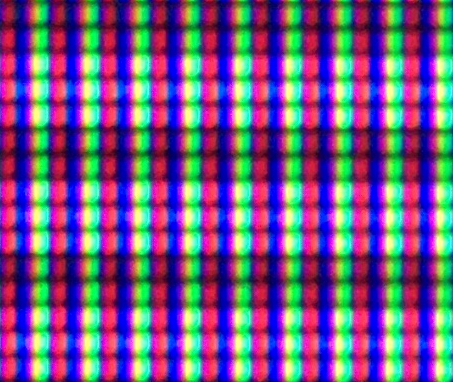
Output2

Now, if I make the shader skip the colour grading / colour space conversion in gamma_correct.h like below (removing the color space conversion * k709_to_XYZ) * kXYZ_to_DCIP3):

include/gamma_correct.h

          else
      {
         //const vec3 dcip3_colour = (scanline_colour * k709_to_XYZ) * kXYZ_to_DCIP3;
         const vec3 dcip3_colour = scanline_colour;  
         gamma_out = LinearToDCIP3(dcip3_colour);

Then the exact same preset gives the following output, which is what we want obviously:
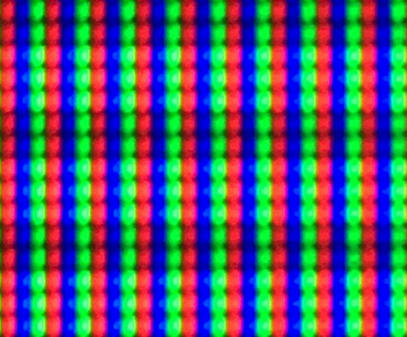
Output1

It would be nice to know whether or not the issue is related to other parts of your code. I noticed you have been incorporating the colour grading stuff from Dogway’s grade.slang, but there’s a big caveat with some of that colourspace code (I’m talking solely about the colour gamut / colour space conversions, I have no opinion on the other stuff). From what I’ve tested with grade.slang the colour space conversions to wide gamut are disfunctional. When I just use dogway’s grade.slang as a standalone it gives me very washed out colors. Much more than what it should be when putting sRGB/709 color space into wide gamut on a wide gamut monitor.

To me it seems the wide gamut colour space stuff in grade.slang was never really tested because dogway didn’t have a wide gamut monitor himself, so no proper way to compare whether 709 to DCI-P3 etc was giving comparable output as just being in native sRGB mode etc.

So again to not give the impression I’m dissing grade.slang, it’s only the colour space stuff in grade that I think should not be used.

My suggestion for you to try and get to the bottom of this would be to remove all colour gamut conversion stuff that you’ve integrated from grade.slang, and instead use the colour space conversion code from guest.r advanced. Which according to my testing seems to work OK. It may save you a lot of headache further along the road.

The guest.r code I’m referring to is in the pre-shaders-afterglow.slang pass, see here: https://github.com/libretro/slang-shaders/blob/master/crt/shaders/guest/advanced/pre-shaders-afterglow.slang

With regards to sony megatron, personally I would be for having all the colour grading and gamma correct stuff in a single pass and not spread out among different passes and parts of the code. Maybe that is in the realm of possibility for the sony megatron?

Preset used with testing: Note that I’ve been testing with a core that has double horizontal pixels, so you may want to adjust the sharpness when used with other cores :slight_smile:

hcrt_hdr = "0.000000"
hcrt_colour_space = "2.000000"
hcrt_crt_resolution = "3.000000"
hcrt_colour_system = "0.000000"
hcrt_gamma_in = "1.760000"
hcrt_gamma_out = "1.759991"
hcrt_red_scanline_min = "0.800001"
hcrt_red_scanline_max = "0.900001"
hcrt_red_scanline_attack = "0.450000"
hcrt_green_scanline_min = "0.800001"
hcrt_green_scanline_max = "0.900001"
hcrt_green_scanline_attack = "0.450000"
hcrt_blue_scanline_min = "0.800001"
hcrt_blue_scanline_max = "0.900001"
hcrt_blue_scanline_attack = "0.450000"
hcrt_red_beam_sharpness = "0.500000"
hcrt_green_beam_sharpness = "0.500000"
hcrt_blue_beam_sharpness = "0.500000"
4 Likes

Here’s an iPhone photo of the new OLED mask using a third party app without AI processing. I think it looks quite good. This is on an LG OLED42C2

5 Likes

Great work @rafan thanks for this investigation, this is really fantastic stuff! I did have a feeling its was to do with this bit of the code, as in the colour space mapping and looking at your snippet of code I think I can see the bug already:

const vec3 dcip3_colour = (scanline_colour * k709_to_XYZ) * kXYZ_to_DCIP3;
         gamma_out = LinearToDCIP3(dcip3_colour);

As in this kXYZ_to_DCIP3 transform is doing a LinearToDCIP3 conversion so we’re effectively doing it twice it looks to me. I’ll look at the code and confirm though. However this doesn’t explain the issue I was seeing as I wasn’t using DCIP3 (I think! hmm). I will look at this as soon as I can I’m just in the middle of a large software project.

As for Dogway and Guest code I certainly based my first attempt on Dogways (stipping out all the stuff I didn’t want/need) but I kind of ditched most of it when I came across the Kronos Groups transforms and various issues I had related to what you’ve said and other things. It may structurally bear some resemblance but the important stuff is all based on Kronos Group examples. I did look at Guest as well and have taken some ideas where they made sense along with other shaders Ive looked at. We all stand on the shoulders of giants at the end of the day and add our own twist.

As for grouping stuff in the same pass this is all down to performance - the first passes are at 240p (fast), the main pass at 4K (slow) and you just have to do things in certain orders rather than all up front. If you have any specific sugeestions I can certainly take a look at them though.

Thanks again for this and hopefully I’ll get some time to fix these issues in the next week or so.

3 Likes

Amazing photo and now I think I can see where those incorrect sub pixels are coming from - they just look like the white sub pixels are being triggered in the whites of eyes so maybe there’s not an issue here! Woo hoo! Does it look alright?

1 Like

Hi @MajorPainTheCactus,

Thanks again for investigating and being around here to answer questions. Now that I’ve been using your megatron a bit more and getting used to it, I’m really liking it. It’s a quite nifty approach to simulating our beloved CRTs on modern display devices. Your work on this is really appreciated.

With regards to the colour gamut stuff, the mapping from one color space into another is done via the CIE 1931 XYZ color space. I don’t see a gamma correction being done in kXYZ_to_DCIP3, while LinearToDCIP3 does it explictly, so I’m not sure something is done twice.

I found the following video a nice visualisation of how the colour gamuts are projected within the XYZ space as it also visualizes the spectral locus. Well worth a watch:

https://www.youtube.com/watch?v=x0-qoXOCOow

Since this colour mapping seems problematic in the shader it may have to do with the way gamma correction is integrated in the gamut mapping? From what I understand the matrix 709(RGB)toXYZ * XYZtoDCI(RGB) maps the 709 “cube” into the DCI-P3 “cube”, such that when you display your content on a DCI-P3 monitor your content is shown as rec709 saturated content.

But how is gamma correctly integrated into mapping one colour gamut into another one? Does the Kronos Group examples spell that out by any chance? There’s both a mismatch in gamma functions and values. I can imagine when using a 709 gamma value of 2.2 and a DCI-P3 gamma of 2.6 (as per spec), is there an implicit gamma correction of 0.4 in this colour gamut mapping or how does that work?

Edit: to complicate stuff my monitor is a wide gamut monitor, targeting DCI-P3, but its default “average” gamma is 2.35.

2 Likes