
Crt_consumer has a slang version? I thought it was glsl-only, damn. That means I can put it through its paces properly 
Thanks for your amazing work.
Are there updates for crt-consumer-1w-ntsc glslp ?
I thought to leave it as it is, simpler and faster. Of course the newer version is better, perhaps if there is demand i’ll port the new version to GLSL too.
You are the best .
I hope update glsl version if you want any time
Yes, there is demand for continuous development and improvement for CRT-Consumer-1w-NTSC-XL.
Here is another composite secret on these 2 screenshots.
Raw rgb, dithering is pretty clear and obvious
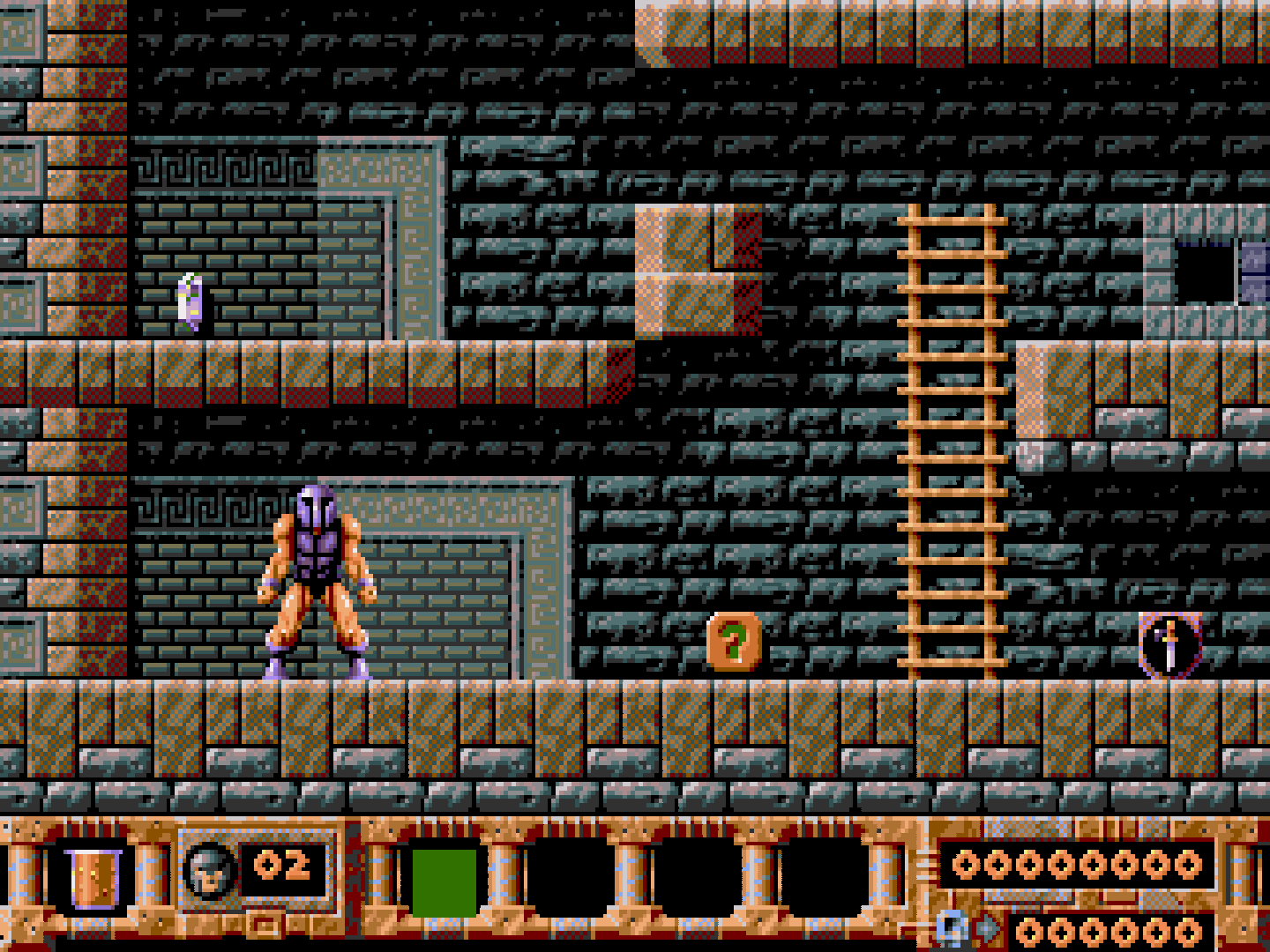
A gray scale representation, look how dithering is almost gone invisible, how close dithered pixels are. Not by luck, that’s the artist’s brilliance there. This is our luma representation in a composite signal. Add some bluriness to this due to luma filters, add the colors of chroma on top, that is more like drawing with a crayon or something due to low bandwidth and you got dithering blend.
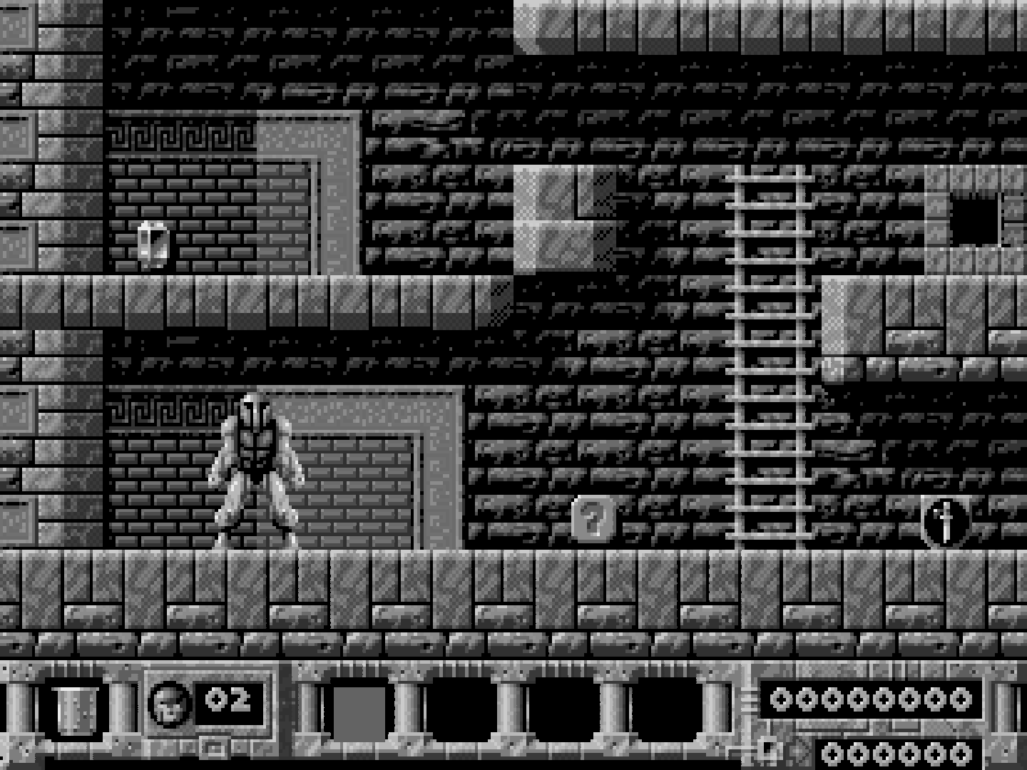
In conclusion, when Luma dithered pixels difference is large it won’t be able to blend. When in S-Video the signal evades some Composite Luma filters as it is clean already so it stays sharper, not blending that easily as in composite.
raw

Real early Genesis model 1 Composite screen capture

crt-consumer-1w-ntsc-XL after reducing Luma bandwidth a bit (and increase comb filter)


Some small changes and added reflection from crt-cyclon
https://github.com/metallic77/shaders_glsl-slang/blob/main/1084s.zip

Even better with the reflection - thank you so much.
Will there ever be a fully modular reflection shader that can easily be appended / prepended to any shader / preset?
Probably hard to implement without messing scanlines etc.
Works better on integer-overscale, “mask” aligns better and creates a more convincing effect.


Thanks for the clarification and for your work - in fact using integer scale max is even better - great work and thanks
A note about masks and why they are mostly inaccurate on most shaders at 1080p (the reason they feel “weird”, you can feel something is wrong).

The gap between the triad of pixels is around the same size of one R/G/B strip, in reality it’s around 20% of the total pixel size. Long story short, in order to be accurate the gap should be minimum 1 pixel and 3 pixels should be used for RGB stripes on every screen, that makes 270 TVL accurate pixels possible on a 1080p, 360 TVL on 1440p and so on. Every other way e.g. CGWG mask etc will create a mosquito mesh pattern as the gap will be same size with all 3 RGB stripes.
270 TVL but accurate on 1080p, around what a cheap low end 14" crt would do.

while 1440p will start looking more like a 20" crt at 360 TVL.

A 4K will do 2160:4 = 540, around a 14" PVM or 1084S but accurate.
So when using another mask like CGWG on 1080p we’re only trying to force the monitor to do something that isn’t capable of doing. The “pixels” are not accurate in any way and will feel weird. Should always be Red-Green-Blue-Black on every screen. Or the other way on BGR panels.
Or RBG on Pre 2026 LG WOLED Panels.

…and tentatively BRG on Post 2026 LG WOLED Panels.
Well yes, whatever pattern is suitable for each monitor. But should be 3 pixels for RGB and 1 for black.
If we research a bit, a Commodore 1702 has 0.64mm dot pitch on 14"
https://crtdatabase.com/crts/commodore/commodore-1702a
A 1080p at 15" has 0.17mm. On the above triad mask we saw that around 1/4 of the actual CRT pixel is occupied by the gap. That means 0.64 : 4 = around 0.16mm. Almost perfect for a 1080p, 1 pixel gap and 3 R/G/B pixels will do proper emulation of that monitor. Total 0.68mm of 1080p will be used for one emulated 1702 pixel. Anything less than 0.64mm dot pitch can’t be accurately emulated by a 1080p monitor.
(Not to mention it isn’t bright enough to do all this properly).
It is true that the gap between triads is low, but there is a gap after each component. From the pic it seems 65% phosphors, 35% gaps (which is indeed about 20*3)

Speaking of accuracy, if I’m right, doing rgbx on an underlying rgb grid gives:
Rxx|xGx|xxB|xxx -> rxxxgxxxbxxx, that’s a 3:1 ratio in favour of gaps!
I think the most “accurate” thing on common RGB/1080p panels is still green/magenta, which at least gives a fair 50:50:
indeed, xGx|RxB -> xgxrxb, gives perfectly spaced pixels but 1440/2=720 triads and 1080/2=540 TVL (thanks cyber for the correction).
Another option would be rbg on RGB matrix: rxx-xxb-xgx, which could be better than rgb on rgb, because when the latter repeats, it couples the last b with the first r, giving weird purple patterns: rxxxgxxxbrxxxgxxxb
…but the eye always has the last word, with or without prescription glasses, in absence of which a special preset may be needed 
The problem with cgwg mask on a 1080p is that it will be 0.17mm for “pixel” and 0.17mm gap, no any real monitor ever did that. Lowering the in between rgb black gaps strength on r-g-b-black will be somewhat more convincing and true actual crt pixel size. Another alternative to save some brightness is to use just a black bar for the gap, cheap but still convincing. Irrelevant but i just recently discovered that
res = res + res * sin(vTexCoord.x * Outputsize.x * PI);
will hold brightness almost 100% even on full strength, as it will add 1.0 on position 0, and subtract 1.0 on position 1 (due to sine nature).
I cannot figure out the 0.17mm dimension by gut, but I am assuming that 0.17mm “pixel” represent the single component and not the whole triad, right?
Green mageta result in: 0.17_,0.17G,0.17_,0.17R,0.17_,0.17B which is the closest thing to the real rgb layout of a crt, at least for the spacing, why not?