I’m developing shaders for a long time. I want to present my last one. It is a CRT shader I made for RetroArch community. Before submitting code or create a pull request, I would like to introduce it.
How can I achieve that ?

I’m developing shaders for a long time. I want to present my last one. It is a CRT shader I made for RetroArch community. Before submitting code or create a pull request, I would like to introduce it.
How can I achieve that ?
I’d just start a thread, with the shader.
Preferably with pictures, maybe some description of the settings.
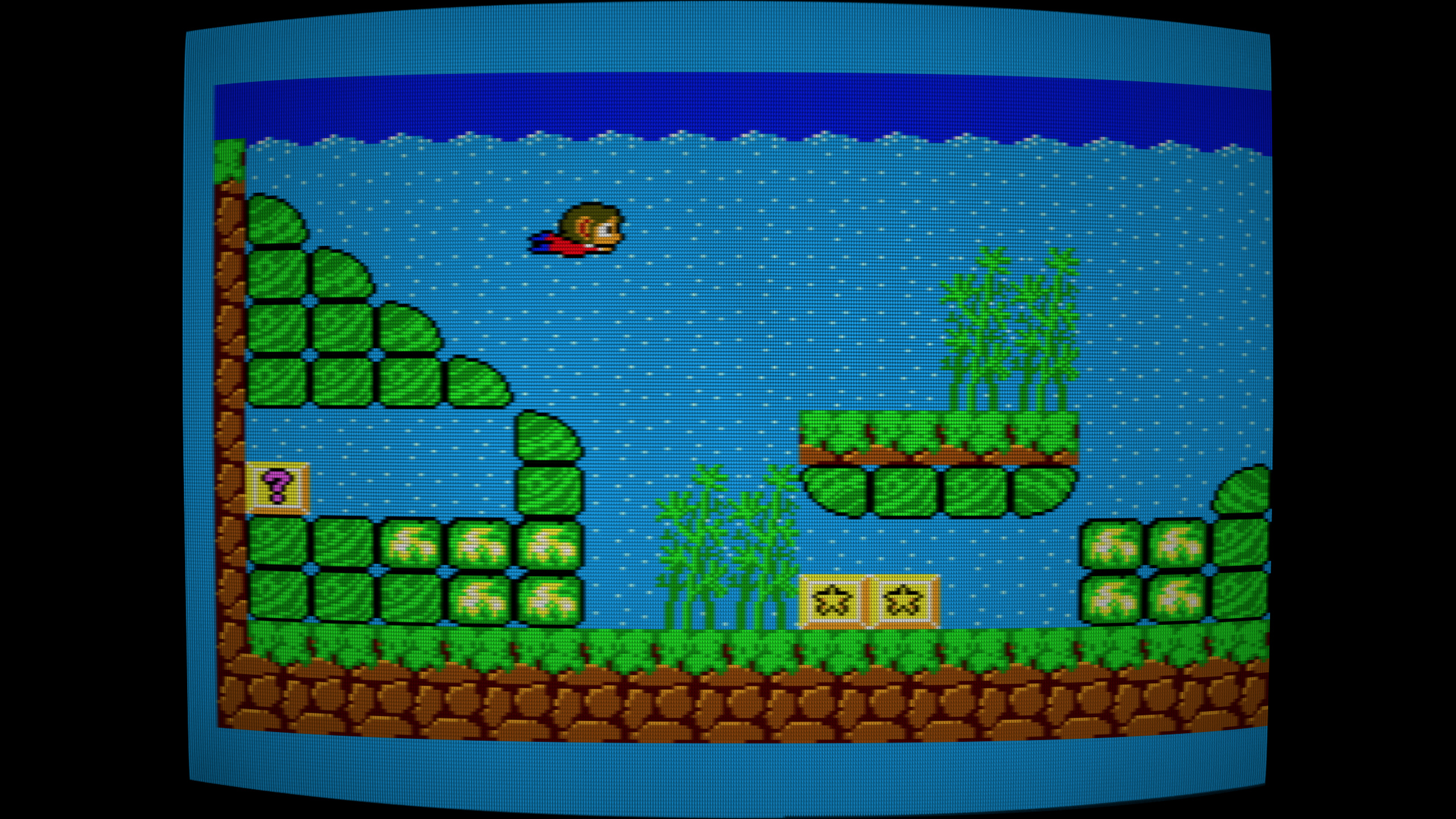
My shader is based on TV Sony Trinitron KV-M1420B. Especially, you can see:
You can see these features through the following screenshot:
Although, all the pixels of the TV input signal (i.e. emulator output framebuffer) are mapped exactly to KV-M1420B pixels @240p. This TV has exactly 439 columns (i.e. 439 x 3 RGB vertical phosphor lines) and screws of PCB are tuned to produce 232,5 scanlines with these timings.
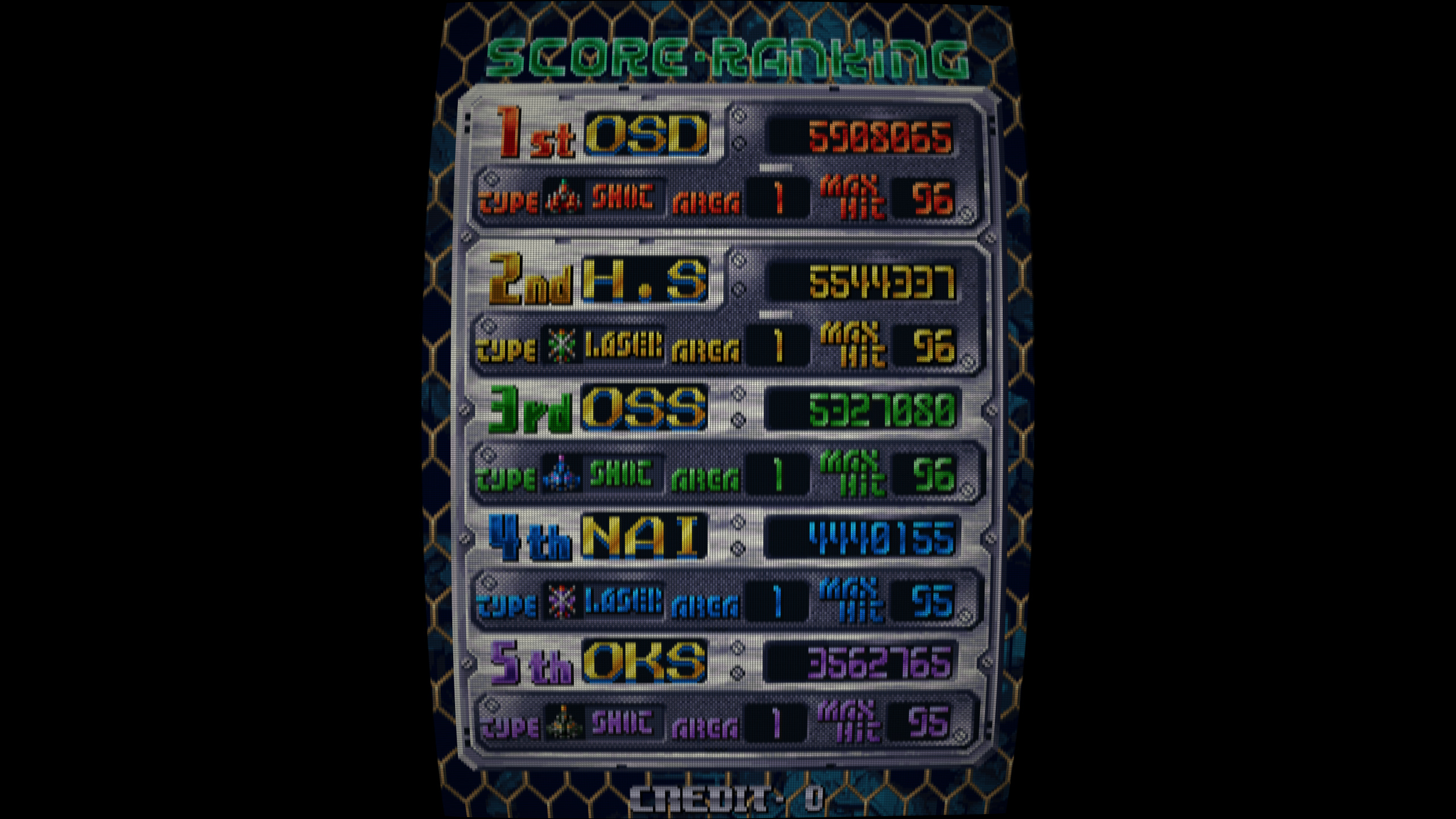
As requested, I take some screenshots of my shader output from RetroArch:
My shader is ready to be submitted to RetroArch shaders repository.
Very cool. I await your pull request 
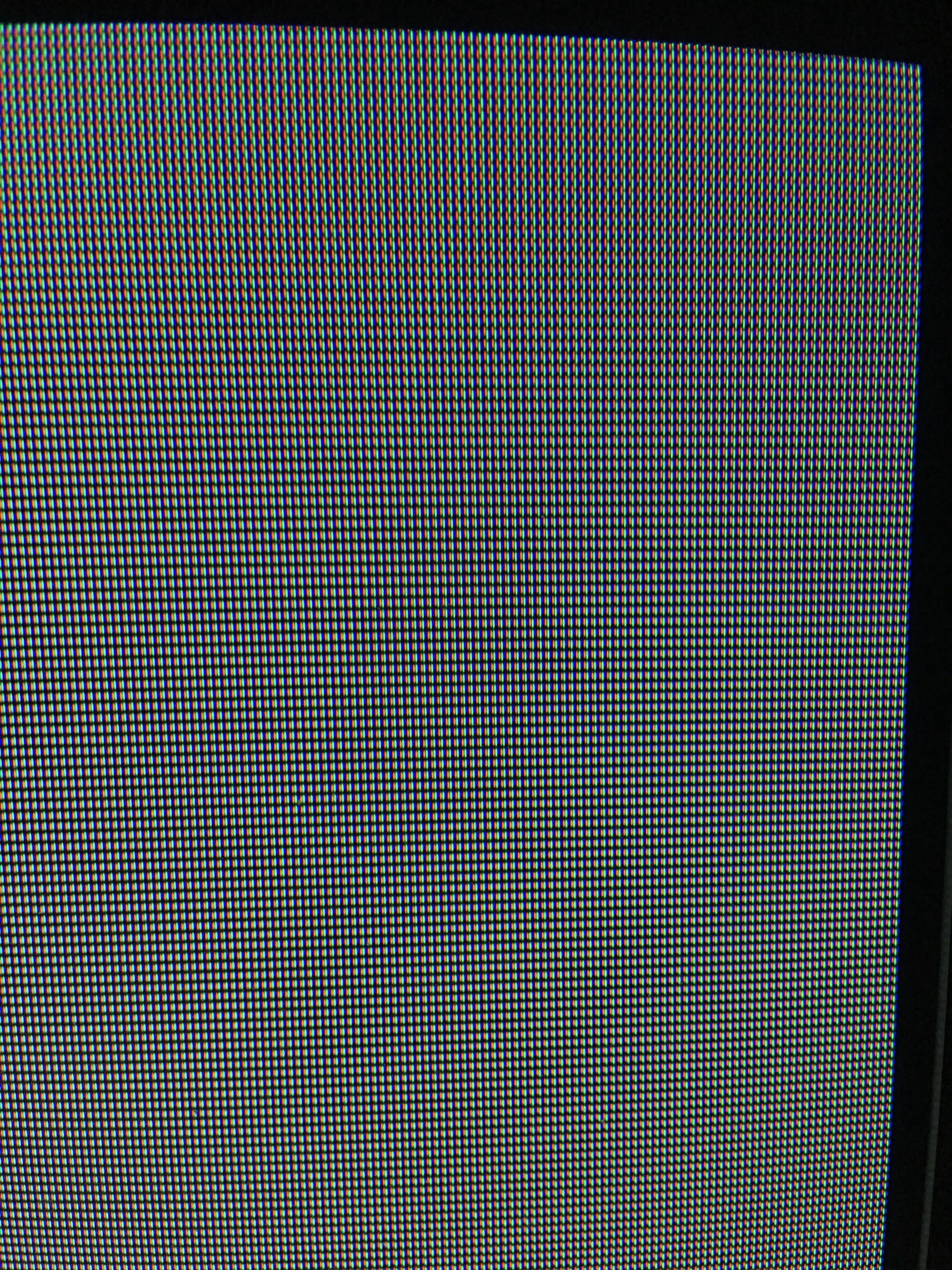
Another feature of my shader is to describe with accuracy the shape of pixels at a certain zoom level. As you can see on the following shoot, the gradient of shape is varying along scanlines and columns.
This is the fact of red, green, blue gun impacts non-regular alignments. You can see it on this closer (quick and dirty) shoot :
Very cool. I just merged the PR, so I plan to try it out some this evening!
I’m impressed that you were able to offload so much to the LUT. @torridgristle has worked on some similar strategies, so I think he’ll be very interested in your work.
I’m happy you like it and I’m happy you plan to spread it I worked many months on it.
Concerning the LUT: My testing version of shader contains 2 RGBA textures The production one contains only one as you can see. Inside my OSX App (which helps me to MAP the screen), I develop a piece of code which gives min and max displacements (magnitude and sign). With this information, I taylor an optimize representation of vector components (i.e. a compact fixed point integer representation). Although, displacements are computed from regular vTexCoord (i.e. texture coordinates fragment shader variable) in order to compress displacements harder.
Can you post (a) link(s) from @torridgristle work ?
Wow, that’s a very cool process you used, actually starting with a high quality photo and extracting data from it like that. I don’t fully understand it, mind you, but I appreciate the scientific approach nonetheless!
Does this require high resolutions in order to look good? Guess I’ll find out soon enough 
I don’t understand the reason for this; is this to reduce moire?
Scanlines which become “vertical” is not my fact It is just my screen observation of this true TV. I try to reproduce it with my shader.
My description “vertical” is poor (sorry), because scanlines are basically horizontal. But if you try to follow them on previous photo, you will see that they tends to change orientation (vertical).
Does this require high resolutions in order to look good?
I submitted 2 shader presets:
If you plan to use shader with a low resolution screen, I advice to use standard preset. The quality will be good. Otherwise, if you plan to use it with Full HD (except cores with vertical orientation), QHD, 4K screens you may use the “sharp” one. The quality will be maximal.
He did the ‘normals displacement’ and ‘blend overlay’ shaders, which control curvature and mask effects, respectively: https://github.com/libretro/slang-shaders/tree/master/reshade
In playing around with your shader, the unique thing it does that I find really impressive is the varying phosphor width as you move from the center to the edges of the screen, which is something you see/experience when looking at an actual curved surface, due to perspective and foreshortening. It really ramps up the verisimilitude of the curvature effect.
Thanks for the link!
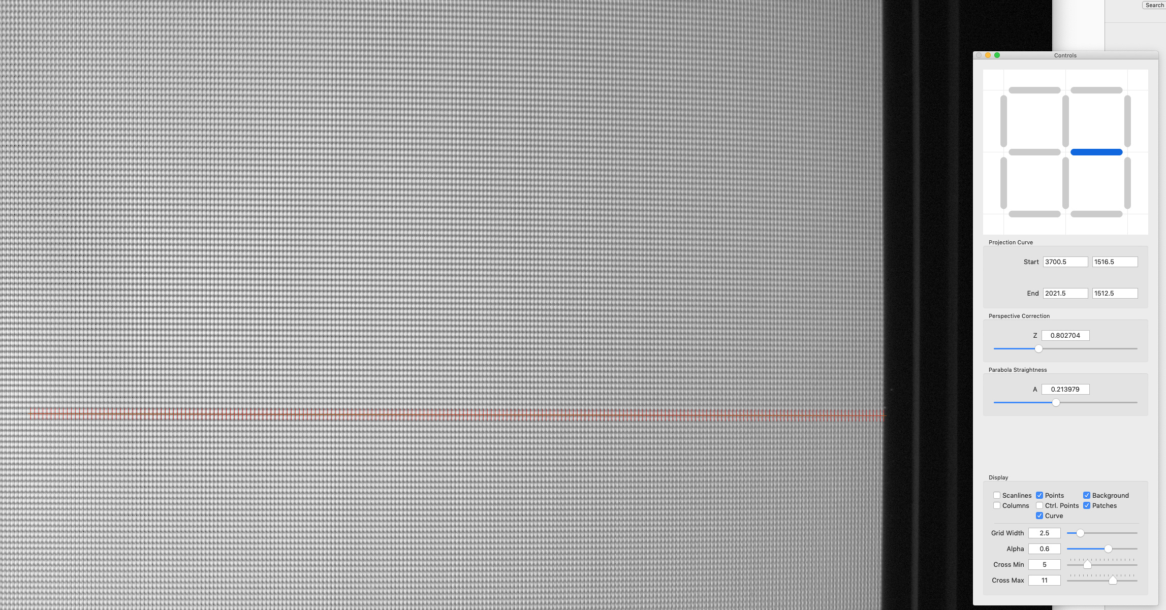
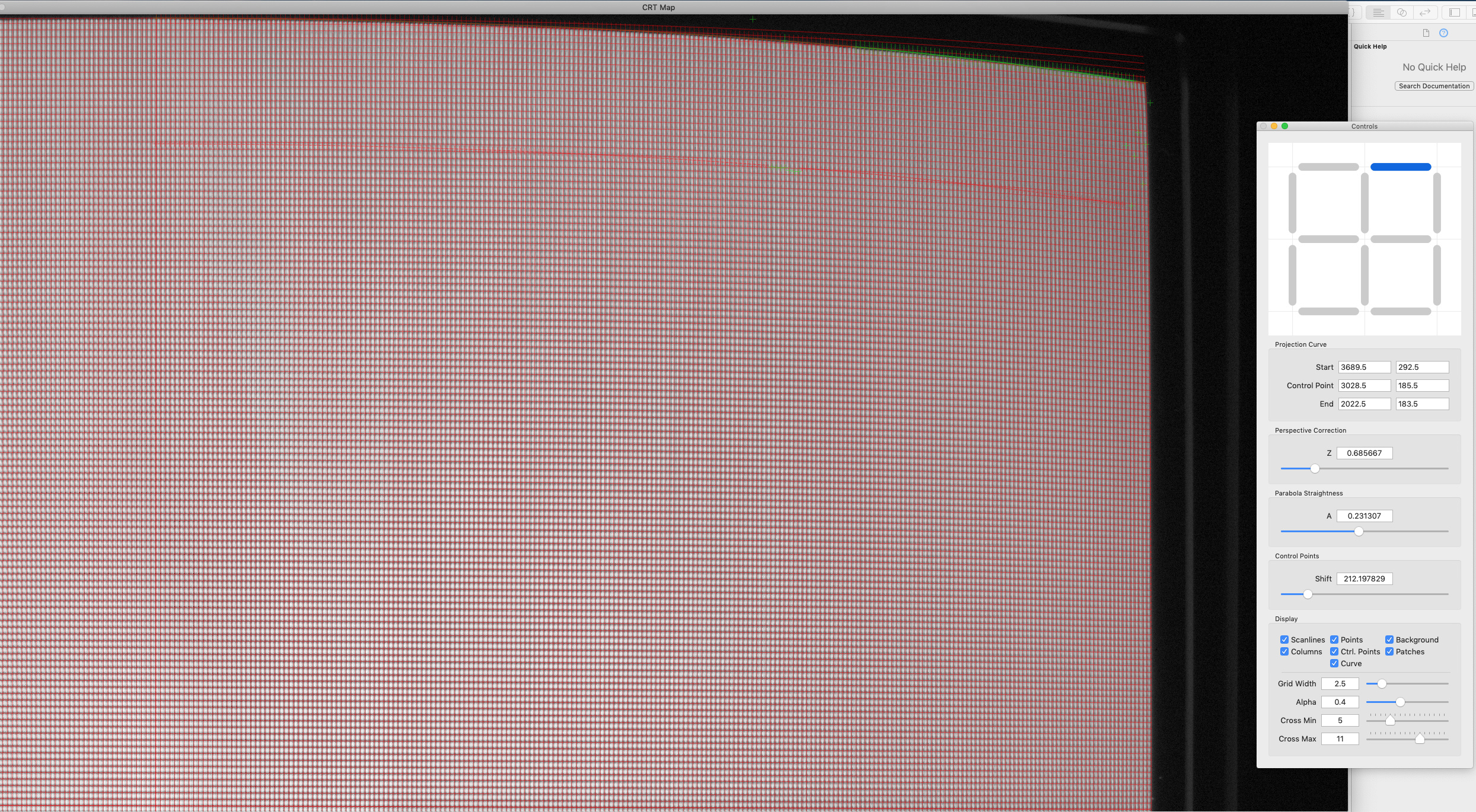
You’re right. I wrote a math model which helps me to place columns and scanlines. Below a screenshot of my app :
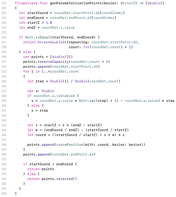
My GUI helps me to find in a visual way constants of my formula that is:Below a piece of code of my app which implements that:
In order to see more about parametrization of my CRT meshes:
I create meshes at maximal resolution 12MP: 4032x3024 in order to maximize accuracy.
So the application makes the mesh with your help?
Yep, I wrote it in this way.
When I began this project, I realize that I have to map 102287 pixels!
I prefer to let my computer do this kind of job
In order to achieve that, I wrote this App.
My job remains to find good math formulas.
This is greatest. Do you plan to release this shader in glsl-shaders?
Thanks!
Yep I plan to code it in legacy GLSL with OpenGL ES compatibility.
Thank you too. We look forward to the day it is released.

 It is available